Luminous monster
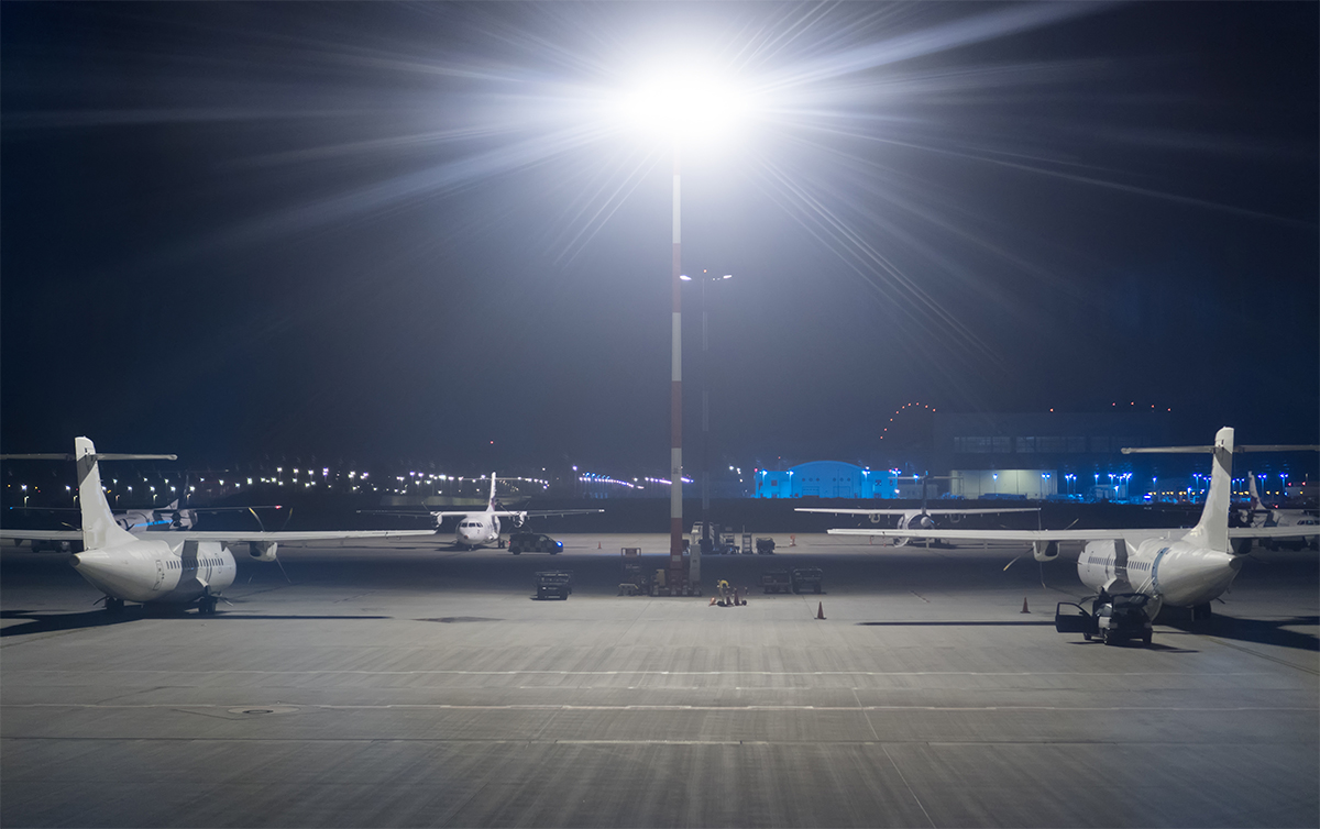
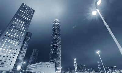
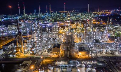
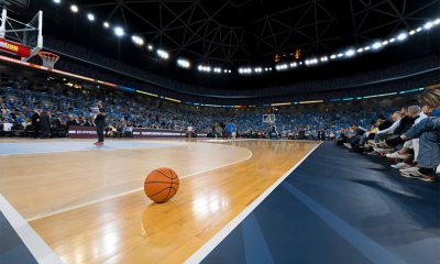
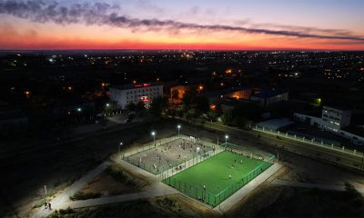
Ultra high power LED flood lights are high wattage lighting systems that produce an exorbitant amount of lumens (80,000+) in a controlled beam for large area lighting or long range projection. These systems are available in wattages from 600 through 1000 to 2000 watts. The large lumen package enables directional lighting to be delivered from high masts or structures. Floodlights mounted on a soaring height may be aimed in a more downward direction to confine the light to the design area, control spill light, and reduce glare. The high mounting height also helps minimize shadows between ground obstacles. The ability to deliver far-field lighting allows the flood lights to be installed along perimeters of target areas or in a remote location so that the lighting installations will not interfere in the functioning of the space. These outdoor directional lights are the exclusive choice of light fixtures for illumination of stadiums, airports, container yards, and other applications with expansive or distant luminous zones.
HID is a huge drain on resource
Ultra high power LED flood lights translate the compelling value proposition of solid state lighting technology into measurable operating cost savings and return on investment (ROI). Traditional high power flood lighting is a drain on resources. It wastes a huge amount of energy, certainly. The inefficiency arises from not only the inefficient power conversion within the light source, but also the optical loss and ineffective delivery of the light to the target.
Metal halide lamps, a type of high intensity discharge (HID) light source, used to be the first choice of light source for high power systems. These lamps are chosen for their availability in high wattages (up to 2000 watts), decent color rendering performance (in comparison to that of high pressure sodium lamps), and improved efficiency over incandescent lamps. In energy intensive applications, however, metal halide systems have lost the struggle with ever-tightening energy code compliance primarily due to their low lighting application efficiency (LAE).
In addition to the lower source efficiency when compared with LEDs, metal halide lighting leaves no room to improve its optical delivery efficiency, spectral efficiency, and intensity effectiveness. The lumen output of metal halide lamps is sensitive to lamp operating position, which makes them disadvantageous in floodlighting applications where optical aiming is a fundamental requirement. Metal halide lamps characteristically require long warm-up and restrike times, experience fast aging under very frequent on/off switching operations, and have restrictive dimming capabilities. These drawbacks prohibit harvesting energy savings of lighting control strategies with metal halide lighting. A constant worry is the excessive lighting maintenance which is usually a large expense.
High wattage lamps have a short life in the range of 3000 hours. At roughly 1000 hours of operation these lamps exhibit lumen depreciation to unacceptable levels. Group re-lamping is required at the end of the bulb life, rather than spot changing individual bulbs, to avoid catastrophic failures envelope failure (bulb explosion).
LED lighting delivers stellar performance and efficiency
Impressive energy savings, extremely long service life, virtually maintenance-free operation, and high lighting quality are the well-known benefits of LED lighting, and have helped the technology to achieve a rapid foothold and an unprecedented boom. LED lighting opens the door to holistic optimization of energy consumption beyond just improvements to light source efficiency. Effective optical design exploiting the directional nature of LEDs can achieve an optical efficiency of greater than 90%, whereas HID fixtures often lose more than 30% of the source lumens within the fixture. Only with a high utilization efficiency does the high luminous efficacy of a light source make sense.
Accompanying the high optical delivery efficiency of ultra high power LED flood lights is the effective distribution of light. The light emitting surface (LES) of an LED light engine can be customized to a specific application, which, in conjunction with the use of high performance secondary optics, enables high uniformity of lighting with minimal waste of lumens. When compounding this attribute, the luminaire efficacy of ultra high power LED flood lights is way ahead of HID fixtures. With instantaneous dimming and on/off capabilities, LEDs are poised to be the catalyst that unlocks the energy savings potential of lighting controls. LED flood lights that incorporate sensors, intelligence and network connectivity provide unprecedented controllability that has a profound effect on driving down energy usage. The energy efficiency benefit of LED lights can be quantified by their long useful lifetime, while reduced maintenance costs from the use of these products over the long service life generate another payback advantage.
Addressing the complexity of LED operation
Though the superior energy efficiency and long life expectancy of LEDs are a proven fact, an LED flood light is in many ways more complex than a traditional lighting fixture. LEDs are characteristically limited to operation under specified ranges for electrical power, temperature, humidity, and other parameters. The efficacy, reliability and other performance metrics of an LED or a group of LEDs are tightly interdependent upon driver circuitry, the thermal management system, and the optical system of an LED luminaire.
To achieve optimal performance and service, select or specify a combination of highly compatible LED packages, heat sink, driver and controls that meet the project requirements. Each and every component must be subjected to extensive design qualification such that all the components will work in unison to deliver the intended value. Most ultra high power LED flood lights are modular systems that use different numbers of LED light engines to provide scalability, versatility, flexibility, and ease of maintenance. Fully integrated systems are available as well. These systems assembly the LED assembly on a single heat sink. They usually come in lower wattages and are typically optimized for a particular application.
Light source
To produce an extraordinarily high output, the flux density and drive current of the LEDs are necessarily very high in ultra high power LED flood lights. The high-power LED architecture therefore calls for the use of high operating temperature capable LEDs. Under high drive currents and operating temperatures, different LED package platforms yield products having different intrinsic characteristics based on package architecture and materials of construction.
High power LEDs have a highly dependable construction, featuring a ceramic substrate which is immune to thermal and photo degradation and provides a high efficiency thermal path to conduct heat away from the active region of the LED. The unique advantages offered by high power LEDs push the boundaries of luminous power and reliability of ultra high wattage lighting systems. The majority of semiconductor dies (LED chips) used to create high power packages are constructed from heteroepitaxial growth of gallium nitride (GaN) on sapphire substrates. However, high power LEDs that grow their GaN on silicon carbide (SiC) substrates offer significant advantages in lumen output and device longevity over competing products made from sapphire substrates because the GaN-on-SiC design creates fewer dislocations and yields more uniform GaN layers. Cree’s high power GaN-on-SiC LEDs deliver reported L90 lifetime projections of 70,000 hours at 105°C of case temperature. In addition to the conventional high-power LED architecture, chip-scale package (CSP) LEDs which have very low thermal resistance will gain prominence in high power applications. The CSP LED architecture remove as many of the packaging elements found in high-power LEDs as possible by making use of the flip-chip design.
Regardless of the technology platform, the performance of phosphor down-converter that applied directly on the LED chip is of vital performance. It must provide the specified spectral behavior which defines the LED’s color characteristics (i.e., color temperature and color rendering), while providing high efficiency down-conversion and resisting high thermal stresses. The color rendering index (CRI) of LEDs used in ultra high power luminaires falls in the range of 70s to 80s, and the correlated color temperature (CCT) is usually 4000K or 5000K. However, the relationship between the light source’s color fidelity, correlated color temperature (CCT) and luminous efficacy is interdependent. A light source with a higher CCT and lower CRI generally have the highest luminous efficacy. The balance of these features to fit a lighting application involves necessary tradeoffs.
High thermal stresses
One of the most challenging issues when operating an ultra high power LED flood light is thermal management. Notwithstanding their significantly light conversion efficiency over HID, incandescent and fluorescent lamps, LEDs throw away more than 50% of the electrical input power which is dissipated as heat within the semiconductor package. The non-radiative recombination of charge carriers (electrons and holes) in the LED junction turns into heat. The Stokes losses of the phosphor conversion of the blue photon to yellow result in heat generation in the phosphor matrix. In a 1000-watt system, for example, more than 500 watts (typically in excess of 600 watts) of electrical power is converted into heat. If allowed to accumulate in the LED package, this huge amount of heat can raise the operating temperature and lead to irreversible damages to the LED. Specifically, overheating the LEDs will accelerate the creation of crystalline defects at the interface of the substrate and epitaxial layer and even pose risks of thermal runaway. Phosphors also degrade at a fast rate under high thermal stresses.
Thermal management
The amount of heat that can be removed from the LEDs largely depends on the design of the thermal path from the die to the air surrounding the luminaire. When designing an ultra high power LED flood light, the thermal transfer path must be adequately dimensioned to handle the applied power load. Thermal resistance along the entire thermal path from the LEDs to the luminaire housing should be minimized by using highly thermal-conductive materials. Implementation of a robust thermal path calls for formation of high reliability, high thermal conduction capacity interconnects (solder joints), and the use of metal core PCBs (MCPCBs) and thermal interface materials (TIMs) with low thermal resistance. The coefficient of thermal expansion (CTE) of the components and materials that constitute the thermal path is a critical aspect that demands attention.
Ultra high power LED flood lights are often exposed to environmental temperature changes as well as drastic fluctuations of system temperatures due to the high thermal loads they generate. Solder joint reliability is a significant factor in minimizing failures due to strains under high CTE mismatch conditions created by thermal cycling. The heat sink is the last and most crucial part of the thermal path as it serves to conduct heat away from the LEDs and then to dissipate the heat into the ambient air via thermal convection and radiation. Thus, the heat sink must be fabricated from a high thermal conductivity material and have large surface areas to interface the other components within the thermal stack and convect heat to the ambient air. The heat sink is typically made from die cast, extruded, or cold forged aluminum. It’s formed in one piece with the housing to maximize thermal performance.
Ultra high power LED flood lights are primarily designed to be cooled through natural convection because of the reliability of passive heat sinks. In addition to lending the passive heat sink a large surface area, an effective aerodynamic design that maximizes the convection heat transfer coefficient is also important. Heat pipes may also be further added to heat sinks to facilitate heat dissipation or spreading.
Driver and control circuitry
The LED driver that operates the constant current LEDs must deliver high efficiency, high reliability with robust specifications for protection against overvoltage, short circuit, overload, overtemperature, and other abnormal operating conditions. An ultra high power LED flood light may incorporate a driver with multiple output channels or a set of drivers that individually operate each modular light engine. The driver circuit should be configured to convert the AC line voltage into a prescribed DC power at an appropriate forward directional voltage while shaping the AC input waveform to achieve a required power factor and low total harmonic distortion (THD). Higher power LED drivers are typically designed as two-stage type switching power supplies that include an active power factor correction (PFC) and a DC-DC converter.
Despite their increased complexity and part count, two-stage SMPS drivers provide the critically higher efficiency power conversion than single-stage systems at higher power levels. Other advantages of using two-stage drivers over single-stage counterparts include higher voltage (e.g., 528VAC) operation, wider input voltage and dimming ranges, higher surge capability, lower EMI signature, and less line frequency related flicker. Power surges, lightning strikes and other electrical events that cause abnormalities in power quality can damage LEDs as well as sensitive circuits and components in LED drivers. Higher power LED drivers must have elevated differential-mode and common-mode surge immunity and transient voltage suppression that safeguard reliable operation of the entire system.
An LED driver can come with different levels of integration with controls, sensors and connectivity for adaptive and/or smart lighting control. It’s often required for the driver to be capable of performing CCR/PWM dimming and responding to the analog or digital signals from a cable bound or wireless controller. Common control protocols for communication between the driver include 1-10V, DALI, ZigBee, Z-Wave, and Bluetooth Mesh.
Light distribution
The optical system that modifies, adjusts, and helps optimize the distribution of emitted light is just as important part of an ultra high power LED flood light as the light source, thermal management system, driver, etc. An inefficient optical design can lead to a waste of a tremendous amount of light emitted by the LEDs of a high wattage system. Compromised photometric performance can be more problematic as it can negatively affect the visual environment. LED flood lights can be designed to produce a wide array of beams, with light distributions ranging from tight spot to wide flood (NEMA beam type 1 to 7) and radiation pattern in axial symmetry or asymmetry.
Control of light distribution from ultra high power LED flood lights is achieved with reflectors, lenses, or a combination of them. Secondary optics for LEDs are commonly designed to provide package-level optical regulation. Oftentimes, a reflector system comprised of an array of small reflectors, rather than a large reflector that sits over the entire LES and only controls the light that is incident on the optic, is used to control the entire initial distribution from the LED sources. To produce smooth NEMA type 1, 2, or 3 beams, the total internal reflecting (TIR) optic that combines the best of both a reflector and a lens is the optimum solution. TIR lenses can be designed in arrays to provide high efficiency optical control for multiple LEDs. However, TIR lenses are often made from acrylic or polycarbonate, which can be thermally challenged in high power applications because phosphor temperatures of high power LEDs can easily be 30°C to 50°C above the junction temperature of the LEDs.
System reliability under environmental stresses
Ultra high power LED flood lights need to be designed to withstand the environment in which they are installed. To prevent moisture, dust, contaminants and insects from entering the luminaire, it’s suggested to seal the luminaire a rating of IP65 or better. The optical assembly is usually protected by a tempered glass lens with full circumference form-in-place silicone gasket. This enclosure should be vented with a microporous membrane breather which can rapidly equalizes pressure differentials arising from temperature cycling and simultaneously provides a durable barrier against liquid, dust, dirt and other contaminants.


Loading...