
What is a machine light
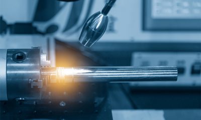
Industrial machine lights are installed inside machinery and equipment to provide task illuminance for various manufacturing processes such as precision CNC machining, electrical discharge machining (EDM), electro-chemical machining (ECM), electron-beam machining (EBM), photochemical machining (PCM), ultrasonic machining, laser cutting, and water jet cutting. In order for a workpiece to be produced with the precision that meets the specifications set out in the engineering drawings or blueprints, attention needs to be paid to many details which have to be revealed by adequate lighting.
Machining operations may be taking place at high speeds and in planes with various orientations. The visual tasks need to be illuminated with a good quantity and quality of light that cannot readily be obtained by off-machinery lighting. Off-machinery lighting whose locations are defined by the building structure cannot penetrate machine tools and is inadequate in illuminance quantity. By placing lighting inside the equipment, obstructions are removed and work pieces can be sufficiently illuminated in every critical angle, allowing machinists to effectively monitor machining processes and to accurately and efficiently complete manual tasks on the machine.
Design considerations
Industrial machine lights need to operate reliably in hostile environments. Machine tools produce the desired workpiece shape usually by cutting, boring, grinding, reaming, shearing, or other forms of deformations. The contact stresses and the temperature at the tool-workpiece interface must be dissipated by various means, which reciprocally affects all components of a machine tool. Machine-mounted luminaires are frequently exposed to constant vibrations, mechanical impacts, flying chips, extreme temperatures, caustic chemicals, coolants and lubricants. Therefore, they should be constructed to withstand in these adverse conditions. In heavy industrial environments, the presence of dirty power, which is primarily switching-related transient surges, produces significant electrical stresses to lighting equipment.
The obligation of industrial machine lights is not just that they must survive these operational and environmental stresses to provide safe, comfortable and productive environment. They must also comply with ever-tightening energy codes and perform dependably to minimize maintenance costs. Balancing all these considerations can make the process of designing and engineering machine lights quite complicated.
Lighting technology
Before the advent of LED lighting, the complexity of machine tool lighting was unable to be fully addressed due to the inherent deficiencies in incandescent and fluorescent lamps. These lamps are short-lived by nature, due to frequent on/off switching, or as a result of fragile construction. The energy inefficiency of legacy lighting technologies not only resides in the poor efficiency of conversion from electrical to optical power, but is also a consequence of high optical losses that occur at the fixture level. The substantial volume and omnidirectional beam pattern of incandescent and fluorescent lamps create a tradeoff between photometric performance and luminaire size. The need for the lights to perform in tight spaces usually leads to compromised light distribution. Incandescent and fluorescent lamps are also deficient in spectral controllability, making it impossible to optimize the color characteristics of light for a specific task.
It’s no accident that LED lighting took the spotlight and has been proliferating the industrial lighting market for every conceivable application. The luminous efficacy of LEDs is way ahead of traditional light sources and still has significant room to improve. The long operational life of LEDs and their solid state nature allow luminaires with high reliability and durability to be created. The small size and optical directionality of LEDs enable precisely controllable optical distributions, high optical delivery efficiency, as well as an infinite variety of design possibilities that can adapt lighting to task needs in even the tightest spaces. The spectral power distribution (SPD) of LEDs can be precisely engineered to deliver the most appropriate combinations of wavelengths that support visual performance. The light source’s full, instantaneous dimmability and high frequency on/off switching capability allow implementation of advanced control strategies.
Light source
LED machine lights come in options of different lumen packages, optical characteristics, performance metrics, functionalities, form factors and sizes. These product variants are dictated by the task size, orientation of the task plane, workpiece characteristics, places of installation, control requirements, etc. They may be linear, square, round, or rectangular in form.
The basic building block of an LED machine light is the LED module. It is typically comprised of an array of SMD LEDs solder mounted on a metal core printed circuit board (MCPCB). The LED module can also be an integrated LED array which is commonly known as a COB LED. The selection of LEDs requires consideration of their luminous efficacy, beam characteristics, color appearance, color rendering ability, and behavior under operational stress conditions.
SMD LEDs built on the PLCC platform are often on the list of priorities because of their high luminous efficacy. The reflective housing and leadframe allows these LEDs to extract light out of the packages more efficiently than other types of LED packages. However, the plastic construction makes these packages vulnerable to thermal degradation. High power LEDs are capable of operation at high operating temperatures and drive currents but necessitate advanced optical design to distribute concentrated lumens evenly over a larger task plane. COB LEDs can produce a very uniform light distribution without the use of secondary optics.
The spectral power distribution of the LEDs is generally biased toward the short-wavelength (blue) part of the visible spectrum. The blue-enriched spectrum gives the emitted light a cool white appearance with the correlated color temperature (CCT) in the range of 4000K to 6000K. White light with a high portion of radiant energy at the blue end of the spectrum enhances concentration, promotes alertness, and improves reactions. The spectral composition also defines the color rendering ability of the light source. A minimum color rendering index (CRI) of 80 is acceptable for machine tool lighting.
Optical control
In direct-lensed or backlit systems, the size and shape of the LED module directly affect the beam pattern and illuminance coverage. Control of luminous flux from the LEDs is achieved either with opal, gaussian or prismatic diffusers, or with lenses or reflectors that extract light directly from individual SMD LEDs and precisely distribute it through key vertical and horizontal planes. LED machine lights may be designed to distributes a narrow, medium or wide beam. Tight beam control necessitates the use of lenses, reflectors, or a combination of them. Illuminance levels and uniformity play a vital role in visual assessment of the task taking place at the machine tool tip. In general, SMD backlit systems must maintain a sufficiently high level of diffusion or illuminate from a sufficiently long distance to achieve uniform distribution of illuminance over the task plane. Failure to deliver uniform illumination will create bright spots on the reflective surface of a metal workpiece, which makes visual spot checks difficult.
The backlit architecture reigns over optical design for LED systems because of the relatively low optical loss when compared with LED machine lights built on the edge-lit architecture. Edge-lit LED panel lights are famed for their high uniformity illumination and softly diffused light thanks to the arrangement of side-emitting LEDs and the use of a light guide that employs total internal reflection (TIR) to extract luminous flux from the LEDs and provides uniform distribution of light toward a diffuser.
Driver circuit
Most LED machine lights use constant current LED drivers to directly regulate the power to an LED, string (or strings) of LEDs, or LEDs in a mix of parallel and series. The LED driver may be powered by alternating current (AC) or direct current (DC) power source. The design of AC-DC LED drivers imposes special considerations as the conversion from the incoming AC line power to the regulated DC output produces additional challenges. All LED drivers with a power rating above 25W need to implement power factor correction (PFC). The drive current will be maintained regardless of changes in operating conditions, in particular the transient surges from the mains supply.
Sinusoidal fluctuations in AC waveforms must be completely suppressed to ensure the drive current has minimal ripples. Large current ripples will cause LEDs to produce temporal light artefacts (TLA) which include flicker and the stroboscopic effect. While exposure to flicker can induce eyestrain and fatigue, the stroboscopic effect can be more of a concern in industrial settings because it can cause the misperception of motion and pose a safety hazard for those operating high-speed rotary machinery.
The DC-DC converter stage can generate high frequency ripples, which should be suppressed as well because the resulting flicker can impact visual performance and health though they’re imperceptible. The DC-DC converter stage requires high speed switching operation which can generate electromagnetic interference (EMI). The switching noise must be filtered and screen because it can adversely affect the surrounding circuit elements. In order for an LED machine light to provide illumination that is highly controllable, the LED driver may be equipped with the step or continuous dimming capability.
Mechanical engineering
LED machine lights are either recessed or surface mounted. An aluminum construction gives the lights mechanical ruggedness. The housing which also acts as a heat sink must be designed to provide an adequately dimensioned thermal transfer path. To increase the heat transfer from the PCB to the heat sink, a thermal interface material (TIM) may be placed between the two surfaces.
The reliability of the solder joint between the LED package and PCB is critical to the dependable operation of LED machine lights when they are subject to repeated vibration. The LED module is protected by a tempered glass lens or a polycarbonate/acrylic diffuser. All points of entry and material transition of a luminaire must be sealed to a high ingress protection (IP) rating. An anodized or conversion coating is applied on the aluminum alloy housing, protecting metal surfaces from corrosion and other forms of deterioration.


Loading...