What is a machine vision light
A machine vision light is used in a machine vision application to facilitate accurate image acquisition by creating contrast between an object under inspection and its background. Machine vision refers to the ability of machines to perform automated image acquisition and analysis. This technology allows industrial machines and equipment to see and identify objects just like the human eye—yet with efficiency and accuracy that are not possible with human operators.
Because of their speed, precision, and repeatability, machine vision systems are proliferating in an increasing number of industrial applications. They are implemented to automate quality control procedures such as dimension verification, parts placement accuracy, defect detection, PCB (printed circuit board) inspection, label placement, label printing, coatings integrity, circuit continuity, and color verification. As a crucial part of factory automation, machine vision is engaged in real-time process control and machine monitoring to react to changes and problems as they develop. A machine vision system can be configured to provide material handling, dimensional measurements, code reading, character recognition, robotic guidance, etc.
Machine vision implementation
A machine vision application is essentially the implementation of a computing system formed by a combination of hardware and software. It utilizes artificial lighting, image sensors, I/O control hardware, camera communication interfaces and image processing algorithms to extract information from captured images. Lighting creates a sufficient amount of contrast to provide the differentiation required by subsequent processing. The lens focuses the luminance (reflected light) to be collected by the image sensor. It also determines the focal length (the distance between the lens’ optical center and the image sensor) and the field-of-view that encompasses the scene. The optical image, which is simply a reproduction of radiant energy coming from the scene imaged, is converted into a digital image by the image sensor. The digital image is then sent to the vision processor for analysis.
The vision processor makes use of an image processing algorithm to accurately interpret the information extracted from an object under inspection against a set of predefined criteria and extract useful information. The result of the analysis is used as decision-making references for operational guidance and corrections. The processor may have discrete I/O points or support data communication by a serial connection via a conventional RS232 serial output or over Ethernet.
Lighting techniques used for machine vision applications
Lighting is crucial for the successful implementation of various image processing methods. These methods include stitching/registration, filtering (e.g., morphological filtering), thresholding, pixel counting, segmentation, edge detection, color analysis, blob detection and extraction, neural net/deep learning/machine learning processing, pattern recognition, barcode and data matrix reading, optical character recognition, and gauging/metrology. Details and features of the object can only be revealed using a particular lighting technique involving a light source and its placement with respect to the object and the camera. Objects with complex geometries often necessitate the use of a combination of different types of lighting.
Some of the commonly used lighting techniques for machine vision applications are back lighting, on-axis or coaxial lighting, structured lighting, dark-field and bright-field illumination.
- Back lighting is used to create a silhouette for maximum contrast that is useful in edge detection, verification of part presence or orientation, and dimensional measurement applications.
- Coaxial illumination is characterized by a beam perpendicular to the camera aperture and is used to evenly illuminate flat reflective surfaces.
- A structured light projects a collimated beam of light at a known angle to achieve an active 3D sensing system.
- Dark field lighting is used to define edges and shapes, highlight surface features, and detect defects on shiny objects by illuminating objects at shallow angles.
- Bright field lighting is designed for high-contrast applications by providing direct lighting onto an object.
- Dome lights provide highly-diffused lighting that creates very uniform distribution of illuminance over an object.
Color requirements
Beyond variations in the angle and light distribution of illumination, many machine vision applications require optical radiation with an appropriate wavelength distribution to create additional contrast, highlight features of interest, or mask irrelevant features that are not of interest and may be confusing to the scene. Color is not inherent in objects. It results from the interaction of the spectral power distribution of a light source and the spectral reflectance function of objects. Under optical radiation of broad spectrum white light, an object will reflect light having the same wavelength as the incident light and the rest is absorbed. Therefore, illuminating an object with selected wavelengths that match the spectral reflectance wavelengths of an object can emphasize its color attribute and achieve the best possible contrast for image processing.
Colors that might disturb image analysis can be darkened with spectrally active light that attenuates these irrelevant colors to maximize the color contrast. For example, red light enhances red features on the image sensor but makes green features appear darker. For monochrome imaging, the light with a narrow band of wavelengths that appear as red, or green, or blue is used. For color imaging, white light that contains a mixture of different visible wavelengths is needed. Infrared (IR) or ultraviolet (UV) light is also used to draw out features of interest that is invisible to the human eye. UV-reflectance imaging, for example, can activate optical brighteners that are contained in materials such as plastics, printing inks and dyes. Infrared cameras are used to detect objects under dark conditions or foreign materials in dark, opaque liquids or food products.
Traditional machine vision lighting technologies
Historically, light sources that had been used most commonly for machine vision applications are fluorescent and halogen lamps. These light sources, however, come with various limitations and deficiencies. The poor energy conversion efficiency and short lifespan of halogen lamps make their phase-out doomed. Compared their incandescent predecessors, fluorescent lamps have a decently improved luminous efficacy. Nevertheless, the luminous flux generated from these lamps is related to the surface area of the source, which makes it impossible to achieve a small lighting footprint. Colder temperatures usually strain fluorescent lighting. Frequent on/off switching can shorten lamp life, which means that they can’t be strobed. Strobe lighting is needed to freeze the motion of a fast moving object. Traditional machine vision strobing systems turned to xenon lamps to produce short pulses of light.
Traditional lighting technologies are deficient in spectral tunability and rely on the use of external color filters to differentially blocking and passing wavelengths. Another incapability of fluorescent and halogen lamps is these light sources cannot produce collimated beam of light for high precision silhouetting and transmissive applications. Collimated lighting is usually accomplished by lasers that produce a tight, structured beam of light at longer working distance due to the nature of stimulated radiation. Fiber optics may provide a safer solution to collimated machine vision lighting.
LED lighting
LEDs are now the staple light source for machine vision applications. An LED emits light when it is electrically biased. Specifically, when an electrical current is applied in the forward direction of the device, holes and electrons are injected into the active layer within the p-n junction where they recombine to release energy in the form of photons. This effect is known as electroluminescence. With electroluminescence from direct band gap semiconductor, the boundary of lighting efficiency, reliability and functionality has been vastly expanded.
LEDs not only operate tremendously more efficiently and last longer than legacy light sources, but also provide a suite of compelling benefits for machine vision applications. The solid state emitters are capable of operating at a high lumen density, which significantly reduces footprint of lighting. The small or compact form factor and optical directionality of LEDs enable precisely controllable light distributions as well as an infinite variety of design possibilities. The spectral power distribution (SPD) of LEDs can be precisely controlled to emit light in almost any color.
LED chips which produce only electroluminescence are narrow-band emitters. The narrow wavelength distribution that is tightly centered about their “peak” wavelength makes the emitted light appear in a monochromatic color such as red, green, or blue. The wavelength of emitted light and consequently its color can be modified by manipulating the band gap of the semiconductor materials that form the multiple quantum well (MQW). The narrow-band emission of an LED can be converted to broad spectrum white light with the desired color rendering quality and color temperature through the application of several phosphors or additive color mixing of multiple primaries.
The service life of LEDs is not affected by high frequency on/off switching. This ability lends them perfectly to strobe lighting applications. As semiconductor emitters, LEDs are inherently dimmable and controllable. The digital nature of LED technology allows lighting to participate in advanced machine vision applications.
System design
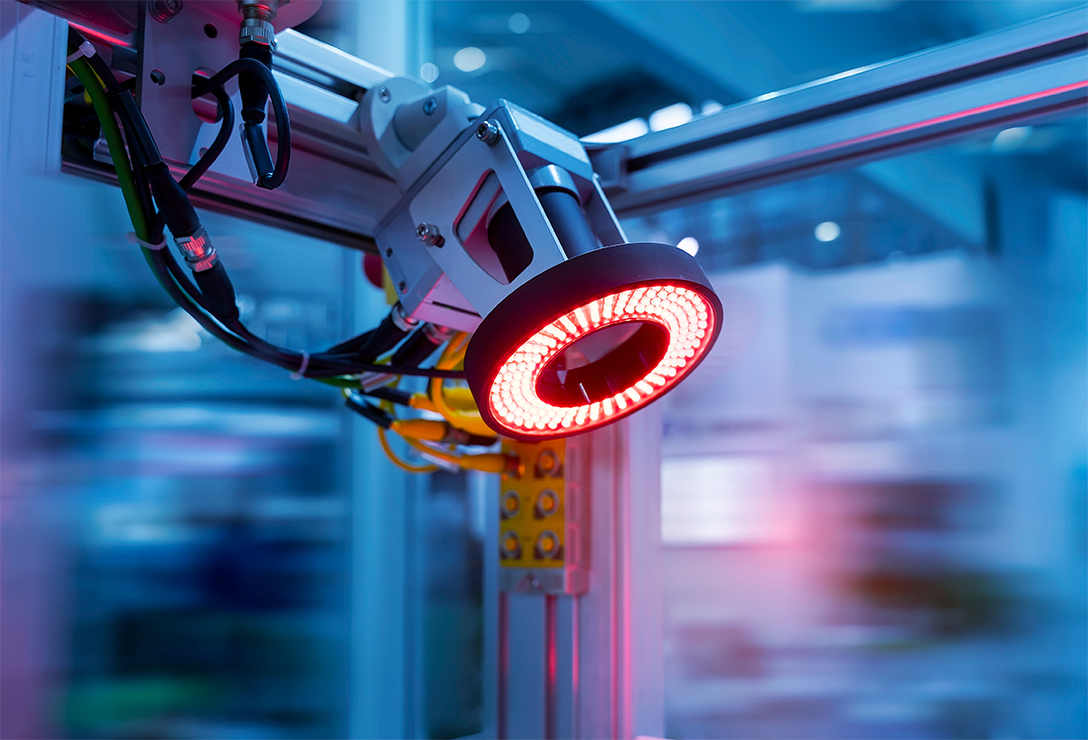
LED machine vision lights can be designed to support the implementation of virtually all types of lighting techniques. The vast range of these products includes, but not limited to, bar/linear lights, ring lights, backlights, dome lights, spot/projector lights, washdown lights, and line scan lights. A typical LED machine vision light comprises one of more LED modules which are assemblies of SMD LEDs solder mounted on metal core printed circuit boards (MCPCBs). The LED module can also be an integrated LED array such as a chip-on-board (COB) LED which is mounted directly to a heat sink without a separate circuit board.
The lifetime of an LED is dependent on the package design and the thermal resistance from solder point to the ambient environment. All elements along the thermal path, including the heat sink, PCB, thermal interface material (TIM) must be designed to allow adequate thermal transfer from the semiconductor die to the surrounding ambient air. The formation of a reliable, thermally efficient solder joint between the LED package and PCB is critical to thermal conduction as well as dependable operation under the mechanical stress of vibrations and impacts that are frequently present in industrial environments.
LEDs are driven with a constant current. Of critical importance is to tightly regulate the amount of power delivered to the LED load so that the LEDs will not be electrically stressed. Some machine vision applications require the LED drivers to have the ability to interpret control signals, such that the connected LEDs can be dimmed or strobed. Secondary optics such as diffusers, lenses and reflectors may be needed to control the light distributions. Industrial applications often necessitate the use of luminaires that have a high level of ingress protection, with ratings of up to IP68.


Loading...