
General description
A dimmable LED light bulb is an integrated LED lamp with internal dimming circuitry that allows the LED bulb to respond correctly to a phase-control dimmer. Although the use of smart light bulbs allows people to exercise dimming control over their lighting all from the convenience of a smartphone, tablet or voice-controlled speaker, manual dimming with a wall-mount or fixture-integrated dimmer to control a lamp-based lighting system stays in demand.
Before the advent of LED technology, light fixtures and light sources were mutually discrete products. Principal functions of a light fixture are to serve as a lamp holder, control the distribution of emitted light, and enhance the look of a space as a design element. A traditional light source is a separate product, commonly known as a lamp, constructed according to universal standards which allow for plug-and-play installation into the fixture and the substitution of lamps by other manufacturers. A lamp due to its need to be replaced after a short service has a base which fits into a socket for receiving electrical power. The lamp-based configuration of conventional lighting systems makes it necessary to run them on two-wire electrical circuits, and thus dimming control has to be based on line signal modulation.
LED lighting rolls out a dramatic transformation
Soon after the invention of the phosphor-converted LED architecture, LED lighting established its performance, lifetime, design and application supremacies over its rivals. Unlike incandescent and fluorescent lamps which produce light through thermal radiation and gaseous discharge respectively, LEDs are electroluminescent devices that produce light from electrical influences. When the p-n junction of an LED is biased in the forward direction, electrons and holes flow across the semiconductor bandgap and recombine in the active region of the diode to release energy in the form of electromagnetic waves. Utilizing the electromagnetic waves to pump phosphors within the LED package can create a spectrum of optical radiation we perceive as white light.
The transition to new technology results in massive energy savings and significant reduction in life cycle costs. What’s more, LED lighting brings a whole new world of design and control possibilities. Modern lighting systems have begun to veer away from lamp-based configurations to embrace an integrated design. An integrated LED fixture is composed of mutually interdependent electrical, mechanical, thermal and optical systems which work together to enable optimal operation of the directly mounted LEDs. Through low voltage wiring or wireless RF communication, the discrete LEDs incorporated in an integrated LED system can be dimmed individually, in individual groups or as a whole to implement a control strategy or to emit light with a tailored spectrum and/or an intended intensity.
LED retrofit lamps
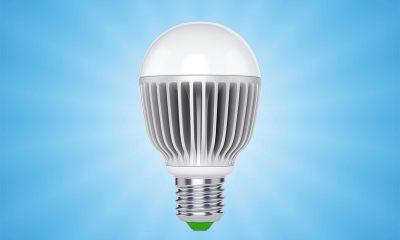
While lamp-based fixtures are dwindling very quickly in new construction homes, there are still territories that have their foothold. To facilitate rapid, safe and cost-effective conversion to LED technology, these fixtures are retrofitted with LED lamps. An LED light bulb is an LED retrofit lamp comprised of an LED module, an LED driver, a heat sink, a medium screw base, and additional mechanical and optical components. The integrated retrofit lamp maintains the physical specifications of an incandescent bulb, but takes advantage of the greater energy efficiency and dependability of LEDs.
As LEDs are semiconductor emitters that allow instantaneous control over a wide range of intensity, they are expected to make intensive use of the dimming function to address the growing demand for controllability and flexibility. However, due to the unique electrical characteristics of LEDs as well as technical constraints imposed by the legacy product design, there are complexities that can hardly be overcome to unlock the full potential of LEDs’ dimming capability in LED bulbs.
Residential dimming technology
Despite all the advances in lighting technology, the method to dim a “dumb” light bulb remains unchanged. A “dumb” light bulb refers to a conventional product that has no wireless RF connectivity to carry control signals. All incandescent, compact fluorescent and LED light bulbs of this type rely solely on the two-wire circuit for both AC power input and dimming control. Dimmer switches that operate these lamps do not have a third wire dedicated to control signal transmission. Dimming operating is made by chopping a portion of the AC sine wave to reduce the RMS voltage delivered to the lamp. This method is known as phase-control or phase-cut dimming.
Phase-cut dimming of light bulbs may be based on forward phase control or reverse phase control. Two-wire forward phase (leading edge) control chops the waveform at the rising portion of the voltage. The dimmer uses a semiconductor switch, e.g., a bidirectional thyristor called triode semiconductor for alternating current (TRIAC), to remove the beginning portion of each half-cycle of AC power for a preset amount of time, resulting in reduced lamp output. Leading edge dimming works very well with resistive loads find in incandescent, halogen and magnetic low-voltage (MLV) lamps. Two-wire reverse phase (trailing edge) control turns off the ending portion of each half-cycle of AC power for a preset amount of time to reduce lamp output. Trailing edge dimmers are used to control capacitive loads such as electronic low-voltage (ELV) light sources and switching mode LED drivers.
A switching mode LED driver represents a capacitive load
LEDs are current driven devices, with the forward voltage varying in the neighborhood of 1.2V to 3.6V. The nearly instantaneous response of LEDs to changing current requires the LED driver to provide tight load regulation for the connected LEDs. The drive current must be controlled within specification boundaries. An application of excessive electrical energy to LEDs can lead to a catastrophic failure. Cyclical peak-to-peak variation in a direct-current waveform (output current ripple) can cause the LEDs to produce flicker and other visual anomalies. Switching regulators are often used in LED drivers to provide a regulated current to drive an LED load. A switching regulator operates at a high switching frequency, often in the range 50–500 kHz, to generate the predetermined magnitude of DC power. It incorporates capacitors for energy storage and ripple voltage filtering. Thus, a switching mode LED driver represents a capacitive load. The problem arises when an LED lamp is used with a TRIAC dimmer which is a purely resistive circuit.
Incompatibility between phase-cut dimmers and LED drivers
In residential settings, most mains dimmers are TRIAC-based. These two-wire forward phase controls work smoothly with resistive loads such as incandescent lamps. Resistive light sources draw electricity directly from the AC grid with a sinusoidal load current in phase with the input voltage. A change in the voltage affects the current, and consequently the light output proportionally. LED light bulbs, on the other hand, draw current from a switching mode LED driver which is typically a capacitive circuit. Switching mode LED drivers draw current from the mains in bursts every cycle (repetitive peak currents) when charging their internal capacitors. The power drawn by a switching circuit typically has a non-linear relationship with the RMS value of its input voltage waveform. Repetitive peak currents drawn by capacitive loads can be 5-10 times higher than their RMS current draw.
Since power factor correction (PFC) is not required only for products that draw more than 25 watts, most LED light bulbs are low power factor LED products that can draw even higher repetitive peak currents. These large spikes in current which may be present at each half-cycle can put a significant stress on the dimmer and may lead to the premature failure in the worst case. Oscillation in the input EMI filters of drivers caused by these high currents may force the TRAIC to turn off and back on repeatedly, which causes flicker in LEDs. Another complication due to the presence of transient currents is acoustic noise in the dimmer. Furthermore, the incompatibility issues between TRIAC-based dimmers and switching mode LED drivers may affect the dimming linearity, dimming range and low end dimming level. In comparison to leading edge dimming, trailing edge AC phase cut control systems do not exert high inrush current but rather generate a dimming waveform that is gentle on the load. This performance advantage makes them useful for switching mode LED drivers and low voltage transformers.
LED dimming technology
Phase-cut dimmers interact only with the LED driver. They do not exert direct influences on the LEDs in a light bulb. The magnitude of electroluminescence produced by an LED in its active region is affected by the drive current. To make an LED light bulb dimmable, a dedicated current control circuit should be incorporated in the LED driver. For constant current LED drivers, two types of dimming circuitry can be used to dim LED loads: pulse-width modulation (PWM) and constant current reduction (CCR).
Also known as digital dimming, PWM dimming manipulates the width of the conducting pulse of the power switch (the duty cycle of the pulsed signal) to control the apparent brightness. It relies on ability of the human eye to integrate or average the pulses of emitted light. CCR or analog dimming works by modulating the amplitude of the drive current fed to the LEDs. In PWM dimming, the duty cycle may be varied from 0% to 100% to dim the LED output over a full range. Because the LED is always driven at the same rated current level, there is no color shift in LEDs. With CCR dimming, the efficiency of LEDs tends to increase at lower drive currents but meanwhile they may not produce a consistent color. Full ranging dimming and full dimming linearity are impracticable with CCR dimming. However, this dimming mechanism is simple to implement and can be deployed in applications with strict EMI requirements.
Dimmer-to-driver collaboration
Dimmable LED bulbs that are operated by switching mode LED drivers generally use PWM to change the light output based on the line signal modulated by a phase-cut dimmer. The LED driver must be designed to understand and interpret a variable phase angle output from the AC dimmer and then adjust the duty cycle of the PWM signal accordingly. An active bleeder circuit or a more advanced mechanism is provided to ensure the repetitive peak current will not stress TRIAC-based dimmers and cause malfunctions such as dimmer buzz, lamp flicker, dead travel and interaction between circuits.
Not all LED bulbs are driven by switching power supplies. It’s now a lot more common to use linear power supplies in LED bulbs. Linear power supplies for driving LED bulbs are preferred for a number of reasons, including complete absence of EMI radiation, space effectiveness and low-overall cost. Most linear LED drivers work well with leading edge dimmers without dependence on additional dimming circuitry because they contain no reactive components and present a resistive load to the dimmers.


Loading...