


 Co., Ltd.")


")


Table of Contents Hide
- 1 What Is a Recessed Downlight
-
2
Applications
- 2.1 Ambient lighting
- 2.2 Task lighting
- 2.3 Accent lighting
- 2.4 Wall washing
- 3 Lighting Technology
- 4 Design and Construction
- 5 Housing
-
6
Trim
- 6.1 Reflector trims
- 6.2 Baffle trims
- 6.3 Lensed trims
- 6.4 Pinhole trims
- 6.5 Wall wash trims
- 6.6 Eyeball trims
- 6.7 Gimbal trims
- 6.8 Retractable trims
- 6.9 Adjustable slot trims
- 6.10 Slope trims
- 7 Aperture
- 8 Beam Spread
- 9 LED Module
- 10 Thermal Management
- 11 Optical Design
- 12 Glare Control
- 13 Color Reproduction
- 14 Correlated Color Temperature (CCT)
- 15 Tunable White
- 16 Dim-to-Warm
- 17 LED Binning
- 18 LED Driver
- 19 Lighting Control

What Is a Recessed Downlight
A recessed downlight is a ceiling-integrated luminaire with the opening of light exit aperture sitting almost flush to the ceiling and directs light downwards at either a perfectly vertical or an adjustable angle. It creates a blanket of light or delivers a controlled beam of light from an architecturally integrated aperture. Recessed lighting is a popular form of architectural lighting because of its inconspicuous aesthetic and cleaner look when compared with light fixtures that substantially extend below the ceiling plane. Recessed luminaires provide functional illumination that addresses not only the needs of the occupants of the space and the activities they perform, but also the aesthetic intentions of the architecture. A recessed downlight distributes light downward or angled in a direct distribution pattern, with the light source regressed into the luminaire to reduce discomfort glare, while the luminaire itself is recessed into the ceiling for an unobtrusive look of ceiling line.Applications
Recessed lighting answers the need for flexibility in lighting design which often calls for a layered scheme in order to offer complete information about a space and to enhance the look of the space as a design element. The layered approach to lighting design maximizes the use of the space and ensures that the interior look has rich visual depth. Downlights are used to provide all three main layers of lighting: ambient, task and accent. These luminaires allow lighting designers and architects to create a cohesive lighting design: they contribute to a balanced lighting composition and simultaneously make lighting not to draw attention to itself.Ambient lighting
Many commercial, hospitality, retail, and institutional applications feature recessed lighting as the first layer for general illumination. As the base layer of lighting, ambient lighting should be evenly distributed to fill in shadows, provide orientation, and set the mood. Recessed downlights are excellent as a source of ambient lighting as they are typically less conspicuous, less visually offensive, less costly, and less prone to vandalism than surface luminaires and pendant fixtures. The use of downlights allows better coordination of fixture placement with the architecture and furniture, thus avoiding a sense of clutter and providing uniform ambience across the space. Recessed downlights are a real workhorse in theaters, auditoriums, conference centers, foyers, and large, open interior spaces where pendant and surface mount light fixtures can be visually obtrusive. Downlights are also a great fit for tight spaces such as hallways, corridors, bathrooms, basements, kitchens, stairways, work areas, utility closets, laundry rooms, and playrooms. In prominent hospitality and residential spaces such as hotel lobbies, multi-purpose event venues, living rooms and bedrooms, downlights are often used in conjunction with chandeliers or flush mount ceiling lamps to fulfil artistic and functional roles for these spaces.Task lighting
Recessed downlights, in particular the directional type, often serve double-duty as task lighting. Task lighting is a fundamental component of a layered lighting design, as it provides sufficient illuminance for users to perform visual tasks safety, efficiently and accurately. Task luminaires fall into two groups: localized task lights and overhead luminaires, Localized task lights include table lamps, floor lamps, undercabinet lights, and shelf lights. Overhead luminaires such as ceiling lights, pendants, troffers, track lights, and downlights, can also be used to illuminate a task. In commercial and hospitality applications where the architectural lighting design concept is embraced, recessed directional luminaires are the predominant choice to provide targeted illumination for accomplishing tasks. These luminaires provide architectural integration and reduce visual clutter that comes with the installation of localized task lights. In open plan spaces and buildings with tall or vaulted ceilings, task lighting is often provided by downlights because other overhead luminaires are very likely to compromise the architectural aesthetics and functionality of the space, while in such spaces table- or furniture-mounted task luminaires are simply not included in the design. The focused, localized beam of light delivered by directional downlights provides task visibility for a specific area, which helps define the spaces, consolidates the layered design, and eliminates the discomfort glare accompanying other overhead luminaires.Accent lighting
Not only utilitarian, recessed downlights can be used to create and complement thoughtful design. Accent lighting adds dimension, depth and drama to a space by highlighting architectural features, calling attention to artwork, emphasizing merchandise features, and visually enhancing whatever deserves to be noticed. Downlights are often designed as adjustable spotlights to deliver concentrated beams of light for accentuating and dramatizing specific objects. Accent lighting establishes the importance of the object of interest through luminance contrast. A rule of thumb is that accent lighting requires at least three times as much illuminance on the focal point as the background illuminance (ambient lighting) surrounding it. Focal glow for creating high visual impact may provide accent factors of 15 or more. A variety of accent lighting applications are accommodated by downlights. In retail stores, boutiques and shows, the contrast ratio of accent lighting to its surroundings elevates the attributes of the merchandise, adds interest and emotional appeal to goods on display, and creates a hierarchy of importance on the selling floor. In museums and art galleries, accent lighting focuses attention, creates visual interest, and reveals form and texture of artworks. In churches, lobbies and historical sites, architectural details stand out when accent lighting is directed to draw attention to them. In hotel rooms, bars and restaurants, accent lights throw flattering light on a specific design element in a room to create an emotionally captivating atmosphere. As part of an interior design scheme for residential spaces, accent lighting is used to create points of interest on houseplants, paintings, photographs, sculptures and other decor elements.Wall washing
Wall wash luminaires are designed to direct light asymmetrically downward to create a blanket or "wash" of light without hot spots or scallops. Diffuse illumination across a vertical surface eliminates shadows and therefore flattens the visual appearance. The reflectance of the surface also increases illuminances and the perception of brightness in a space. Homogeneous lighting from a luminaire is critical to achieving an even washing effect and maximizing fixture spacing. In addition to the optical design of luminaires, luminaire placement is important for optimal distribution of light. Wall wash luminaires are typically placed at a distance from the wall that is one-fourth or one-third the wall height.Lighting Technology
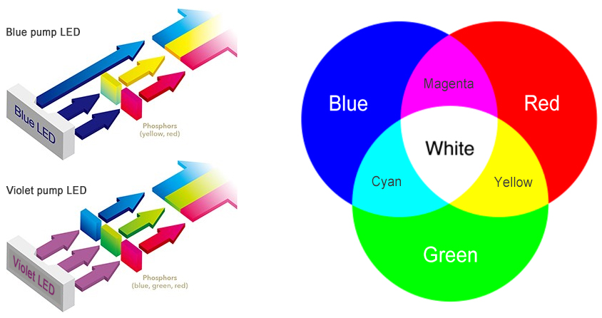
Modern downlights thrive on LED technology. The massive migration to LED lighting has been primarily spurred by high conversion efficiency from electrical to optical power and long lifespan of LEDs. Phosphor converted LEDs deliver a luminous efficacy potential of 255 lm/W and a practical efficacy approaching 200 lm/W, which is significantly higher than that of legacy halogen, fluorescent and metal halide lamps. When operating LEDs in a thermally and electrically optimal environment, their L70 (70% lumen maintenance) life can be as long as 200,000 hours. The quantum leap in performance and reliability is attributed to injection electroluminescence within semiconductor devices. Specifically, carrier electrons from the n-doped semiconductor layer drop down from the conduction band and recombine with holes from the valence band of the p-doped semiconductor layer in the active region of the diode, when a forward bias is applied across the doped layers. Radiative recombination of electrons and holes releases energy in the form of photons (packets of light).Injection electroluminescence in the active region of the semiconductor diode yields narrow-band emission, resulting in a color light, such as red, blue, green, or violet. Indium gallium nitride (InGaN), a direct bandgap semiconductor, is the material of choice for manufacturing LED chips with high internal quantum efficiencies. Because of the relatively narrow spectral distribution of InGaN-based blue or violet LEDs, a wavelength converter is required to partially or completely convert the electroluminescence for an output with a broad emission profile, which is perceived as white light by the human eye. The highest efficacy LEDs today are phosphor-converted blue InGaN LEDs, which are often referred to as blue pump LEDs. By pumping single narrow wavelength light into phosphors of different compositions within the device package, white light with different spectral qualities can be generated.
Tailoring the spectral power distribution (SPD) of white light thus became very convenient with LEDs. The SPD of a light source specifies the amount of radiant energy (or power) emitted at each wavelength. It establishes the color metrics of the light source: color rendition and color appearance. Since LEDs offer greater flexibility for adjusting the SPD, LED downlights can produce light with color rendering performance comparable to incandescent radiators and even natural daylight at any correlated color temperature (CCT). This is a highly desired feature for interior lighting applications, as the color quality of a light source affects how humans appreciate an object or an environment.
Another major spectral advantage of LEDs is that they produce no infrared (IR) radiation and a negligible amount of ultraviolet (UV) emission (< 5 uW/lm). Ultraviolet and IR radiation can be very damaging to light- and heat-sensitive materials, such as museum artifacts, retail merchandise, and grocery produce.
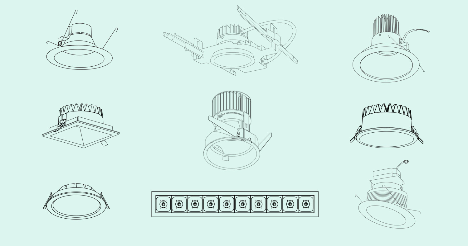
Design and Construction
A recessed LED downlight can be a lamp-based luminaire or an integrated LED luminaire. A lamp-based downlight uses a light source that has its optical performance characteristics built into the light source. The light source can be a reflector bulb (GU10, MR16, PAR, R, BR or ER) or a general service bulb. Lamp-based LED downlights are typically the retrofit type luminaires or entry-level products. Despite the plug-and-play convenience of using self-contained light sources, these luminaires are less found in architectural and accent applications. There are many considerations of knocking out the lamp-based design for LED downlights. Incorporating an LED bulb in a luminaire not only is a practice of over-designing, but also compromises optical efficiency and makes precision beam control for many specific applications a daunting task. In contrast to the over-designing of the luminaire itself, a majority of LED bulbs currently available on the market are under-designed in order to drive the cost down. These products use bare-bones driver circuits, inefficient heat sinks, and low-performing LEDs. LED bulbs are often labeled by industry insiders as crappy products because their light quality, lumen maintenance and color stability fall far short of what people have expected from LED lighting.Today when it comes to LED downlights it’s most appropriate to talk exclusively about integrated LED downlights. These recessed systems are designed and engineered for optimal operation of an LED module and also efficient regulation and precise distribution of its luminous flux. In conjunction with custom designed secondary optics, an array of discrete LEDs can be designed to provide uniform ambient illumination, a single-point LED can create a spot beam with the highest punch possible for accent lighting. The integrated design allows the LEDs to make full use of the luminaire housing for heat sinking, thereby keeping the LED junction temperature under control and maximizing the performance potential of LEDs. In systems with co-located drivers, miniaturized LEDs or compact LED arrays make space for an electrical compartment that can accommodate full-featured driver and control circuitry while isolating thermal stresses from the LED module. Since LEDs have interdependent thermal, electrical, and optical characteristics, a holistic approach is necessary to achieve the full potential of LED lighting.
An integrated LED downlight generally consists of a housing, an LED light module, a driver, and a trim. The driver may also be externally mounted so that the luminaire can be designed with a low profile to fit in very tight plenum spaces. The housing that holds the light module and trim in place extends into a ceiling so that the aperture and trim can sit flush with the ceiling line. In a common configuration the light module and trim is maintained in a fixed downward position aligned with the center longitudinal axis of the cylinder housing. This type of downlights is typically used to provide ambient illumination. In another configuration, the light module is in a fixed position but an optical device is used to direct some portion of the light at higher angles onto wall surfaces for wall washing applications. In adjustable recessed lighting systems designed for accent lighting, the light module and trim are mechanically unified or rigidly fixed to each other and the assembly can tilt and rotate such that light is directed at an angle relative to the longitudinal axis.
Housing
In general, LED downlights (hereafter referring to the integrated type) are self-contained lighting systems that are designed for recessed installation through retention systems, such as torsion springs and friction blades, without using additional mechanical structures. These luminaires typically come with a fixture-as-heat-sink design. The aluminum housing works simultaneously as the heat sink and is exposed in the plenum space for maximum convective heat transfer.In North America however, downlight luminaires are installed in dedicated housings available in either new construction or remodel units which are designed and constructed as per the UL1598 standards. Remodel recessed housings are designed for retrofit applications where back side of ceiling is not accessible. The aluminum housing can be installed through an opening in the ceiling from below and secured in place by torsion springs and pressure clips. New construction housings are supplied with bar hangers that provide stability and support on joints and T-bar grid ceilings. They must be installed prior to the enclosure of the ceiling so as to coordinate the location of recessed downlights with joists, ducts, wiring, or plumbing that may also be located in the ceiling. New construction housings are divided into four categories depending on whether they can be installed in direct contact with insulated ceilings and whether they are airtight:
- Non-IC (non-insulation contact) housings are designed as plaster frames or trays. They are installed in ceilings where no insulation is in contact with the downlight and the insulation must be kept a minimum of 3 inches (7.6 cm) from the fixture. These housings are provided with over-temperature protection to reduce the risk of thermal overload.
- Non-airtight IC (insulation contact) housings are constructed in a way similar to the non-IC type housings but allow direct contact with ceiling insulation by enclosing luminaires with a metal barrier or enclosure, commonly known as an IC box. The IC box does not impose airflow restrictions.
- Reduced airflow IC (insulation contact) housings can be used where insulation is in direct contact with the housing. An IC box that encloses the luminaire has a construction that reduces airflow but is not guaranteed to any particular specifications (e.g. < 2 cfm under pressure of 1.57lbs/ft²).
- Ultra-airtight IC (insulation contact) housings are designed to prevent air leakage from heated or air conditioned into the unconditioned areas. The IC boxes of Ultra-airtight IC housings share a similar design and construction with reduced airflow IC boxes. However the ultra-airtight IC box has caulking applied to all interior joints and the underside of the plaster frame may be gasketed so that airflow is restricted to applicable specifications.
Most metal components, such as plaster frames, bar hangers, vertical‑adjustment brackets and butterfly brackets, of new construction housings are made from galvanized steel. Aluminum plaster frames are for use in very damp locations, or installations where non-magnetic properties are required (e.g. in MRI rooms). The heavy gauge bar hangers include a pair of metal bars which are extendible to fit between 16” spaced joists, and 24” spaced joists. They slide within two opposing sides of a plaster frame or butterfly brackets. Butterfly brackets are die-formed sheet‑metal brackets that accept commercial bar hangers and are mechanically attached to the vertical‑adjustment brackets through a slot.
Both new construction or remodel housings often come with a junction box which is typically disposed laterally of the housing, plaster frame or outboard of the plaster ring. The junction box is kept a certain distance from the luminaire in order to keep the driver from overheating. The junction box and its snap-on covers must be at least 0.05” thick if made of steel, and 0.09” if made of aluminum.
Trim
Trim refers to the light exit assembly that provides optical regulation and aesthetical enhancement for a recessed downlight. The light exit assembly is designed to maximize delivered lumens, shape the radiation pattern of LEDs, conceal the LEDs from direct view, and seal the ceiling cut out for seamless architectural integration. Various types of trims are available, depending on the light distribution, visual cutoff, and/or optical aiming requirement.Reflector trims
Reflector trims produce a highly luminous aperture that is suited to high ambient lighting applications typically found in commercial facilities, office buildings, high ceiling spaces, and task areas. Reflectors sit over the LED modules and regulate luminous flux from the light source at a large angle. Specular reflectors exhibit a high reflectance but can cause visual discomfort when the aperture is excessively large. In some cases, semi-specular or diffuse reflection may be employed to produce highly efficient integrating chambers for capturing and distributing light from high flux density LEDs, while minimizing aperture brightness.
Baffle trims
Baffle trims trap extraneous light and soften aperture brightness using a series of light-absorbing, deeply grooved ridges. Baffles are installed in the lower inside portion of the light cone. Downlights with baffle trims are typically used in intimate and living spaces such as cocktail lounges, night clubs, restaurants, living rooms, dining rooms, and bedrooms. Black baffle trims are used to dilute the brightness from recessed cans for a high level of visual comfort but at the expense of significantly compromised luminous efficiency. White baffle trims create a brighter aperture, but blend with white ceilings when they're off.
Lensed trims
Lensed trims serve two purposes. The trim houses a plastic or glass lens that protects the LEDs and electronic components from moisture and dust ingress. This type of trim is commonly referred to as a shower trim which allows the downlight to be used in wet locations such as bathrooms, showers, closets, and areas that are exposed to water or moisture. Lensed trims are a characteristic design of low profile downlights that enable recessed lighting for ceilings with a limited plenum clearance. Low profile downlights feature an ultra-thin fixture depth and are powered by off-board drivers. A diffusing lens made of polycarbonate, acrylic or glass distributes the light by diffuse-scattering for homogeneous general illumination over a large area while softening the harshness of LED light and offering impact resistance.
Pinhole trims
Pinhole trims are designed with deep set optics and small openings to deliver a concentrated beam for focusing attention on single points of interest. The precise beam created by the pinhole trim is great for accentuating architectural elements, highlighting merchandise features, drawing out the best traits of artworks, or creating focal points exactly where it's needed. Aside from accent lighting, pinhole downlights can also be utilized for task lighting applications such as above tables, workspace, cabinetry, and other locations where a directed beam with minimal spill light and discomfort glare is desired.
Wall wash trims
Wall wash trims allow recessed luminaires to produce light in an asymmetrical light distribution, bathing a whole wall in a smooth, even gradation of light or creating a varied, scalloped look for a vertical space. Vertical illuminance visually increases the size of a room and makes the space more pleasant and welcoming. Wall washing eliminates shadows and therefore flattens texture and hides imperfections in wall surfaces. Wall wash luminaires are usually placed at a distance from the wall that is one-fourth the wall height.
Eyeball trims
Eyeball trims provide maximum flexibility of optical aiming for accent lighting applications. The trim can tilt up to 30° and rotate around its axis 360°.
Gimbal trims
Gimbal trims feature 35° tilt adjustment and allow up to 180 degrees of rotation. The trim starts flush with ceiling, but part of the light will be cut off by the fixture housing when the trim is tilted at full range.
Retractable trims
Retractable trims, also referred to as "elbow" or "scoop" trims, can be retract out of the housing for vertical aiming up to 90°.
Adjustable slot trims
Adjustable slot trims have a slot aperture that allows a focused beam of light to be angled at up to 35 degrees within the fixture. The trim allows up to 180 degrees of rotation. The adjustable light assembly is concealed by the flat trim.
Slope trims
Slope trims, as the name suggests, are designed specifically for slope ceiling installations. Slope ceiling downlights keep the beam aimed straight down rather than following the slope of the ceiling.
The trim is the only visible portion of a recessed downlight and therefore it offers the greatest potential for harnessing aesthetics. Decorative trims that bring an ornamental glow to the ceiling make recessed downlights call attention to themselves. The reflector can be designed to either contrast with the ceiling or blend into it. Plastic or metal trim rings (also known as trim flanges) provide a clean installation by covering and sealing the edges of holes cut in the ceiling for recessed luminaires. While flanged trims offers a more traditional ceiling appearance, flangeless trims accentuates a seamless and sophisticated aesthetic with a smooth, mudded-in ceiling appearance.

Reflector finish (Image courtesy of Cooper Lighting)
Aperture
The aperture is the opening at the bottom of the recessed downlight through which light exits the trim cavity. The aperture size of round downlights can be as small as 1 inch and as large as 8 inches. The size of the aperture determines if the light source is camouflaged or a high perceived brightness is created. Also, the aperture size should match the scale of a room. Commercial, open plan spaces usually need large-aperture downlights, whereas small residential rooms are typically suited to luminaires with medium or small apertures. Downlights with a round aperture create a rotationally symmetrical light distribution. Square or rectangular exit apertures are also available for producing beam patterns that are similar in shape to their exit aperture.
Beam Spread
For recessed downlights, controlling the light distribution is just as important as the light output and luminous efficacy. Depending on the beam spread, LED downlights fall into categories of spotlights and floodlights. Floodlights that have a beam spread above 60° are referred to as having a very wide flood beam. These luminaires are generally used to provide general lighting or wall washing. Ultra-thin, flat panel LED downlights radiate across a beam spread of up to 120°. Illuminance uniformity is of one of the most important design parameters for wide beam flood lighting. A smooth, uniform light distribution eliminates shadows in the neighboring areas of two beams on a flat surface, which allows to create an even washing effect on vertical surfaces or avoids visual fatigue due to continuously adapting between two different horizontal luminance levels. An exceptional uniformity of horizontal illuminance also maximizes spacing criteria (SC).
Recessed downlights that provide accent and task lighting use very narrow spot (5° or smaller), narrow spot (6°-9°), spot (10°-19°), narrow flood (20°-25°), flood (30°-40°), or wide flood (55°-60°) beams. Beam or beam spread in directional lighting applications refers to the field angle, an angle between the two directions in the plane in which the intensity is 10% of the maximum beam intensity. Lumens that fall within the field angle is considered to be useful lumens. Lumens falling outside the field angle are called spill light which should be eliminated or minimized. The field angle alone cannot define the beam performance because it tells only how wide the light is spread. The angle at which the half-maximum intensity occurs is used to measure where most of the light is going. This angle is commonly knowns as beam angle or the full beam width at half-maximum (FWHM).

Image courtesy of Acuity Brands
Accent lighting has varied requirements on the field-to-beam ratio which dictates if the beam is hard or soft. A hard beam has beam angle very close to the field angle, which results in a sharp drop-off at the edge and makes the beam look clean and crisp. A soft beam has a small beam angle and fades gradually out toward the edge of the field beam. A hard beam creates pinpoints accentuation for a dramatic emphasis on the object. A soft beam provides smooth transition from dark to light and thus better visual integration with the surrounding.
The luminous intensity at the center of a symmetrical beam is called center beam candlepower (CBCP). The optic design objective of most narrow-beam accent lights is to deliver high CBCP rather than the amount of lumens projected onto the object. A spot beam with a high CBCP packs enough of a punch for a strong visual impact. On the other side, when spot, narrow flood or flood beams are used to illuminate a task, uniform light distribution far outweighs punch.
LED Module
An LED module, also known as an LED array, is an assembly of LED packages on a printed circuit board (PCB), with additional thermal, mechanical, and electrical surfaces that allow the LED assembly to be integrated with other system components such as the driver and heat sink. The LED module may include a single LED package such as a chip-on-board (COB) LED, or a ceramic-based high power LED. This type of modules is generally used for directional lighting which requires a high flux density light source for focused, localized illumination. The LED module can also include a number of mid-power LED packages or chip scale packages (CSPs) connected in a series string or in a mix of parallel and series for constant current designs. Multi-package LED modules are typically used to create a flood beam for wall washing or ambient lighting.The type of LED packages that an LED downlight uses can significantly affect system performance and reliability. The variety of LED package platforms exhibits diverse thermal behaviors, optical performances, drive current densities, and board interconnectivity. Ceramic-based high power LED packages attach a large LED die to a metallized ceramic substrate that creates a high efficiency thermal path for effective extraction of heat from the active region of the LED. This design allows high power LEDs to operate at very high currents, resulting in high optical flux densities for a powerful, high CBCP beam that's most wanted in spotlighting applications. In contrast to high drive current, high operating temperature capable ceramic-based high power packages, mid-power SMD LEDs that are packaged in an industry-standard PLCC package have poor lumen maintenance and color stability. While mid-power LEDs have an attractive price point and initial lumen/watt, the poor thermal stability of their reflective housing that contributes to a high efficiency light extraction and significant thermo-mechanical mismatch between the leadframe and the die (CTE and Young's modulus) rule out these plastic packages in high power and high flux density applications. Mid-power LEDs are mostly used in downlights that provide ambient lighting. Their discrete nature makes them advantageous in producing beam patterns with a low flux density but a wide distribution.
COB LEDs are the most preferred type of packages for use in recessed luminaires that provide accent lighting. In a COB package, an array of electrically interconnected semiconductor dies are bonded onto a metal-core printed circuit board (MCPCB) or a ceramic substrate. Direct die bonding shortens the thermal path, reduces thermal resistance, and eliminates superfluous, thermally unstable package materials that are used in PLCC packages. The improved thermal design allows the huge amount of thermal energy to be rapidly drawn out of the LED junction and enables the LED to operate with less color shift concerns when compared with PLCC packages. COB technology makes it possible to deliver a high lumen package from a single LED package and thus simplifies system design and integration. The most attractive selling point of COB LEDs, however, is that the highly homogeneous light that these multichip LEDs emit. A large light emitting surface (LES) and close spacing of the dies make it possible to create a highly controllable beam with high flux density, outstanding illuminance uniformity, and exceptional color homogenization. The form-factors of COB LEDs has been standardized by the Zhaga Consortium. This addresses the complexity of luminaire development, in particular the optical design, with a wide range of COB products.
The reliability of the interconnect between the LED package and PCB is a critical engineering point of the LED module. In most LED module designs, the LED packages are reflow soldered to printed circuit pads of an MCPCB. A multitude of factors can directly affect the formation and reliable performance of the solder joint. The reflow process which occurs when the boards move through the oven and the solder paste melts must maintain a tight control on the time and temperature profile to facilitate wetting and formation of a consistent intermetallic layer. The solder alloy is required to have high creep resistance so that the solder joints will survive repeated thermal cycling under high coefficient of thermal expansion (CTE) mismatch conditions. To eliminate solder variability due to hand soldering, COB LEDs can be attached to heat sinks using Zhaga-compliant holders. The solder-less connector solution provides an easy, fault-free way to integrate LEDs into their designs and can help with aligning a secondary optic with the LES.
Thermal Management
Notwithstanding the dramatic improvement in the conversion efficiency from electrical to optical power over traditional light sources, LEDs convert only between 40 to 50% of the electrical power they are fed into light. Because the LED is a closed system and it does not radiate thermal energy in the form of infrared light, the part of electrical power that is not converted into light is dissipated as heat within the semiconductor package. If the heat generated during LED operation is allowed to accumulate, a variety of temperature-dependent LED failure mechanisms will be triggered or accelerated due to the overheating of semiconductor layers, bonding wires, phosphors, encapsulant and other packaging materials. Thermal ageing of encapsulant/phosphor composite and growth of thread dislocations at the interface of the substrate and epitaxial layer are two major failure mechanisms that accelerate lumen depreciation (efficiency loss) and the unwanted change in the spectral characteristics (color shift) of LEDs.As a result, thermal management becomes an essential factor for unlocking the full potential of an LED downlight throughout its entire functional life. The ultimate goal of system thermal design is to keep the junction temperature below the maximum rated operating temperature even at higher levels of power. Three variables that affect the junction temperature are drive current, thermal path, and ambient temperature. Thermal engineering of an LED luminaire is to build a thermal path capable of transferring heat away from the LED junction to the ambient at a rate that outpaces the rate at which thermal energy is introduced to the junction under the worst possible operating conditions, including driving the LEDs at the maximum rated load and operating the LEDs at the maximum allowable junction temperature. Typically, the thermal path begins at the semiconductor junction, and travels via the solder joint, PCB, and heat sink before finally reaching the ambient air. The challenge lies in reducing thermal impedance of the assembly, which includes thermal resistance of all components along the entire thermal path, and all the associated interface resistances.
As noted previously, interconnect (solder joint) reliability is a crucial aspect of system engineering. When it comes to thermal management, solder joints can be a competitive candidate for the bottleneck in a thermal path. A robust interconnect is thus a prerequisite to building an effective thermal path. While solder joints enable the LED to electrically and thermally interface with the system, the PCB, which is most often an MCPCB, provides a large surface area to spread the heat to the heat sink. An MCPCB, also known as an insulated metal substrate (IMS) board, is constructed using copper foil laminated to an aluminum plate with a dielectric layer attached inbetween. The dielectric layer sandwiched between two metal layers offers high through board thermal conductivity and low thermal impedance yet still provides high electrical isolation between the circuit and aluminum cladding. To reduce interface resistance between the MCPCB and heat sink, a thermal interface material (TIM), which can be a grease, pad, phase change material, graphite or indium foil, is placed between the two components.
Recessed downlights rely on the thermodynamics of conduction and convection, rather than on fan-assisted or other active cooling methods, to transfer thermal energy away from the LED module. Passive cooling solutions utilize heat sinks to conduct heat away from the LEDs and then to convect it to the ambient air. Thus, maximizing material thermal conductivity and convective cooling capacity of the heat sink are essential. The driving mechanism for natural convection is the physical movement of molecules induced by the density differences between the hot air near the surfaces of the heat sink and the cooler air surrounding the heat sink, that is, the convective heat transfer rate is determined by the heat transfer coefficient and the area exposed to air flow. However, in recessed applications the velocity of the air flow is low and correspondingly so is the heat transfer coefficient. A practical solution is to increase the surface area of a device that is in contact with the surrounding air.
Aluminum heat sinks made through the die casting process exhibit a good thermal conductivity (90 - 115 W/mK), but what makes more sense with aluminum die casting is that this process allows heat sinks to be fabricated with a complex geometry while maintaining excellent corrosion-resistance and dimensional stability. Heat sinks are often designed with integral fins which effectively increase surface area while allowing the heat sink to remain confined to a given footprint. Downlight heat sinks can be also made from extruded or cold forged aluminum, which comes with a significantly higher thermal conductivity (200 W/mk for cold forged 606x aluminum, 200-215 W/mK for 6xxx aluminum alloy extrusion).
Optical Design
LED downlights have varied requirements on light distribution and beam control. Optical design for downlights can encompass the entire spectrum from reflectors, lenses, refractors, and diffusers all the way to components for integrated optics.Recessed luminaires that produce a wide flood beam usually employ reflectors to regulate luminous flux from the light source. It makes sense to use a reflector design when the size of the light source is large and cost is a consideration. The light source can be a large LED module soldered with an array of discrete LEDs, or a COB package consisting of an array of dies under a common phosphor layer. Low profile downlights use polycarbonate (PC) or polymethyl methacrylate (PMMA) to distribute luminous flux from the LEDs uniformly to all directions thus do not create an image of the light source. Untra-thin profile downlights use edge-lit technology to deliver a fully luminous panel of soft, visually comfortable light. Light from the edge-mount LEDs is transported and evenly distributed across the surface of a light guide panel (LGP) through total internal reflection (TIR). The LGP refracts the beams down towards a diffuser, which spreads the light out for soft, homogeneous illumination.
Directional luminaires that provide narrow beam light for accent illumination place high demands on precision of optical control. Both reflectors and lenses can be used to shape the radiation pattern of LEDs. To produce narrower distributions with very sharp cutoff control, light source is deeply regressed into a specular reflector for a large shielding angle. To provide better distribution of luminous flux to the desired direction, the reflector can be segmented into multiple small surfaces (facets). The facets that come with different angles of rotation cut up the light from the source and direct the narrow bundle of light passing through it in a specific direction to form a concentrated beam. Reflectors often produce a light distribution which has peak intensity at central axis but also a relatively large area of scattered light around CBCP. Also, reflectors are inefficient in narrowing the FWHM divergence angle of LED module with a large LES, as they will only control the light that is incident on the reflective surface and ignore the portion of light that does not hit the optic.
Lenses provide high flexibility for developing custom optics that allow for control of light with high efficiency and precision. Lenses that sit over a LED to alter the beam of light can be a single optical element such as a glass, PC, PMMA or silicone spherical lens. A compound lens, which is an array of single optical elements with a common axis, enables capturing of the light in a completely controlled way and guiding it into the specified distribution through key vertical and horizontal planes. Injection molded from transparent polymers such as PC, PMMA or silicone, a TIR optic is a compound array of refractive and reflective lenses capable of collimating virtually all the radiated light for creating very tight beams with FWHM divergence as small as 10 degrees. TIR optics create uniform hard beams or smooth soft beams with minimal spill light. This type of optics can be used to regulate the luminous flux from both small LEDs and COB LEDs which have a large footprint. TIR optics have gained a great favor over specular aluminum reflectors or vapor-coated plastic reflectors for its ability to collimate and steer light produced by the large footprint COB LEDs which has a typical FWHM divergence angle of 120°, and to deliver an extensive range of optimized beams, from narrow to medium, wide and extra-wide angles.
Downlights may be designed with an accessory holder that accommodates field-changeable optical accessories for further beam optimization or modification. The most common types of optical accessories includes softening lenses, spread lenses, and light reduction screens. Softening lenses remove hard edges and spread the light in an even, diffuse fashion. Spread lenses elongate the beam into an elliptical pattern, useful for accenting rectangular or irregular shaped items. Light reduction screens provide a simple, mechanical method to reduce light output without altering the initial color temperature if the light source.
Glare Control
The directional nature of LEDs gives LED downlights an inherent beam control advantage in spotlighting and floodlighting applications. However, the accompanying glare issue due to concentrated emission of LEDs poses a significant challenge to luminaire design. The high intensity light source can produce a sensation of irritation or pain. High luminances within the field of view do not affect visual performance but cause discomfort, which is obviously not acceptable in commercial, retail, hospitality and residential spaces where lighting is designed to render a visually comfortable environment. Discomfort glare is controlled by eliminating excessively high luminances from the line of sight. Recessed LED systems usually position light source a distance away from the opening of light exit aperture so as to ensure a minimum shielding angle for glare cutoff. In addition to maintaining deep source regression, the aperture brightness should be reduced to a minimum. Aperture brightness is controlled by reducing luminance of the lower inside portion of the luminaire's aperture. This can be done by using less specular reflectors and dark-color baffles. Additional glare control devices such as honeycomb louvres are also used to reduce the angle of line of sight to the source.Recessed luminaires are assigned a Unified Glare Rating (UGR) to assist lighting designers and architects in predicting glare during the design phase of a project. The practical range of the UGR scale is between 10 and 30. A lower number on the UGR scale indicates a lighting system with less glare. A UGR of 19 is considered as acceptable for reading, writing, training, meetings, computer-based tasks. When performing meticulous jobs such as technical drawing or to create a luminous environment that is of extremely visual comfort, a maximum UGR of 16 should be maintained. In North America, the Visual Comfort Probability (VCP) method, wherein the highest rating is 100, is used for evaluating glare from a lighting system. VCP values of 70 and 80 translate to UGR values of 19 and 16, respectively.
Color Reproduction
Color reproduction is an important component that goes into the design of recessed lighting for ambient and accent applications. How true or natural the colors of objects or scenes look under the light source can dramatically affect how people appreciate the objects or interact with the environment. In retail environments such as fashion stores, cosmetics shops and luxury retail stores, accurately rendered colors of merchandise can trigger impulses to buy and alter shopping behavior. In museums and art galleries, capturing the colors of exhibits as accurately as possible is especially a priority because colors are an indispensable information carrier. In hotels, restaurants and residential spaces, whether the colors are rendered attractively can have significantly different effects on how the spaces are visually experienced and how people socialize or relax.
The color rendering ability of a light source depends on the distribution of light energy across the wavelength range of the visible radiation spectrum (typically from 380 to 780 nm). The spectral power distribution (SPD) of a light source specifies the amount of radiant energy emitted at each wavelength. Color rendition refers to the interaction of an SPD and spectral reflectance functions of an object. In order to reproduce the colors of various objects faithfully, the light source must deliver radiant power fairly broadly and uniformly across the visible spectrum. Natural daylight is the ideal light source for color reproduction because it contains high levels of every color in the spectrum. How closely the color rendering of a natural light source is matched by an artificial light source is often measured using color rendering index (CRI). Daylight has a perfect CRI (Ra of 100). Thermal light sources, such as incandescent and halogen bulbs, are called "incandescent radiators". These light sources are recognized as having excellent spectral quality and the ability to faithfully reproduce the colors of objects. Since the phase-out of incandescent radiators due to their poor energy efficiency, the colors of the world rendered by their successors was significantly distorted. Fluorescent lighting, the mostly commonly used incandescent successor in interior applications, has a typical Ra of 70-80 and performs poorly in reproducing highly saturated colors whose rendering performance is not reported in the Ra metric.
The advent of solid state lighting (SSL) based on the LED technology addressed the long felt need for a light source that delivers energy efficient lighting with excellent color rendition. But even with LEDs, the tradeoff between color rendering and luminous efficacy has remained. The SPD of light emitted by an LED chip (or LED die) has a narrow width between about 10 nm and 30 nm. This results in a monochromatic radiation (colored light). In order to produce broad-spectrum white light which delivers radiant power broadly across the visible spectrum, light emitted by LED chips is partially or fully converted through the process of photoluminescence. Phosphor-converted LEDs, which employs InGaN emitters to provide the blue pump for phosphor excitation, can simultaneously achieve the efficacy and cost targets when the emission spectrum for saturated colors is significantly narrowed. On the other side, LEDs that produce high intensity radiant power at all wavelengths of the visible spectrum must down-convert a large portion of shortwave length light to longer wavelength emissions. The more shortwave length light is down-converted, the lower the luminous efficiency of an LED due to the Stokes energy loss. While utilizing a blue LED to pump phosphors within the device package is by far the dominant white light architecture for its high energy conversion efficiency, white light may also be produced with full phosphor approach using violet pump LEDs. Violet pump LEDs have a relatively lower efficacy compared with blue pump LEDs because full wavelength conversion is involved. Nevertheless, full wavelength conversion from violet light yields an SPD that spans the visible spectrum from violet through deep red, with greater amount of radiation at each wavelength, resulting in a light source with color rendering performance comparable to that of sunlight.
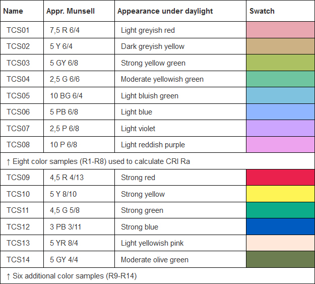
As efficacy usually outweighs color rendition, the interior lighting market is flooded with LED luminaires with a typical Ra of 80. This CRI is generally considered the minimum acceptable value for most interior applications. It is, however, unacceptable for color-critical applications in museum, hospitality, and high-end retail settings. Since the general color rendering index Ra is an average of the special CRI (Ri) for only the first eight of the reflective samples that have medium color saturation, light emitted by most 80 CRI LEDs can cause color distortion because of the missing wavelengths that reflect the highly saturated color samples from R9 to R14. When the color rendition metrics of light source are only available as CRI calculations, values for R9 through R14 should be specified separately in addition to CRI. A high CRI without a strong R9, a deep red sample, can render fabrics, paintings, cosmetics, skin tones, foods and beverages with a dull or lifeless appearance. When the recessed luminaires are intended for high color fidelity lighting applications, a minimum CRI of 90 and an R9 value above 75 is suggested. Since CRI is purely a color fidelity metric and does not always correlate well with visual evaluation, dozens of alternatives to CRI have emerged. The Technical Memorandum TM-30 provides an evaluation framework for quantifying both overall average properties (color fidelity, gamut area) and hue-specific properties (fidelity, chroma shift, hue shift). The Color Quality Scale (CQS) system addresses the limitations of CRI method by using more color samples, and takes into consideration three aspects of color appearance including color fidelity, chromatic discrimination and observer preferences.
Correlated Color Temperature (CCT)
Light is radiant energy capable of producing a visual sensation that affects the pleasantness of a space and subjective interpretations of brightness. Correlated color temperature (CCT) or chromaticity refers to the color appearance of the light source. This metric offers a measurable color attribute that enables lighting designers to dictate warmth or coolness. A warm light source exhibits a CCT in the range of 2700 K to 3500 K. A cool white light source has a CCT above 4100 K. Those with a CCT between 3500 K and 4100 K are commonly referred to as having a neutral white appearance. The selection of light source color temperature is guided by several variables, which may include emotional moods, visual tasks, room color palette, circadian rhythms, and architectural aesthetic goals. In restaurants, hotels, theaters, homes, etc, the universal choice is a CCT on the warmer side of the Kelvin scale. Laden with red and orange wavelengths, warm white light make spaces more comfortable and people more relaxed. The warm glow imparts a feeling of intimacy and relaxation that inspires conversation. Low short-wavelength radiation or absence of blue light with low CCT lighting ensures uninterrupted release of melatonin which allows for a regenerative sleep. Most commercial applications use light sources of 3500 K to 4100 K or an even higher CCT to make people feel more energized, motivated and refreshed. Museum applications may employ low CCT light sources to prevent photochemical damages caused by radiation of shorter wavelengths, which're rich in cooler white light.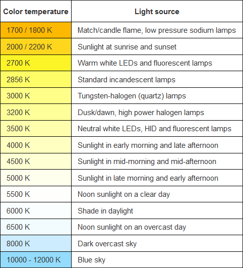
Tunable White
Human centric lighting (HCL) is designed to bring the dynamics of natural daylight into interior spaces. It simulates the spectral quality and light intensity of natural daylight over the entire day using tunable white technology, thus synchronizing the circadian rhythm to the natural day/night cycle. Light not only provides visual sensation in humans, but also has a biological effect. Our master biological clock has evolved to keep track of the 24-hour rhythm of the ambient changes. Suprachiasmatic nucleus (SCN), a group of cells in the hypothalamus that control human circadian rhythms, respond to the changes in brightness and light color over the course of the day through the neural conduit formed by the intrinsically photosensitive retinal ganglion cells (ipRGCs). Upon receiving neurological signals transmitted by the ipRGC photoreceptors, the SCN signals to other parts of the brain that control the release of hormones such as melatonin, dopamine, cortisol, and serotonin. The spectral sensitivity of the ipRGC photoreceptors peaks at short wavelengths around approx. 480 nm. This blue wavelength sensitivity indicates that high CCT light, which emits more short-wavelength radiation, is more biologically effective at modulating circadian entrainment.Tunable white LED downlights mix LEDs with different CCTs in one assembly and provide a continuously adjustable range of color temperatures from, e.g. 2700K to 6500K for human cenrtic lighting. Tracking the natural rhythm of daylight, tunable white lighting mimics the natural fluctuation in daylight. During daytime, the LED luminaires can be programmed to produce blue-enriched neutral or cool white light which suppresses the secretion of melatonin and promotes dopamine, serotonin, and cortisol production. Thus, cool white, high intensity lighting helps adjust the body to “daytime mode”: raising concentration levels, increasing motivation and commitment, creating sensations of pleasure, improving cardiovascular efficiency and muscle coordination, etc. In the evening, the tunable white luminaires change in both the level and spectral composition of light to simulate the appropriate levels of irradiance and spectrum of ambient light during sunset. Under the radiation of blue-depleted low intensity, warm white light, the pineal gland is triggered to release melatonin in the bloodstream. Uninterrupted release of melatonin in the evening and during the night is critical to cell metabolism and proliferation, proper functioning of the immune system, and reducing diabetes, depression and seasonal affective disorders.
Dim-to-Warm
Dim-to-Warm refers to the ability to change color temperatures of light when a lamp is dimmed. This feature simulates the "warm glow" dimming characteristic of an incandescent lamp which warms up from 3300 K to 1700 K as its intensity is reduced. The cozy shift from the reddish-yellow color of candle flame to the warm shade of white light gives users the flexibility to set the mood and allows them to create the look and feel that align with an event or a theme. Dim-to-Warm LED downlights mix LEDs of two different colors for CCT tuning and uses a current sensing system to synchronize the adjustment of CCT and brightness. The use of Dim-to-Warm LED systems in restaurants, hotels, and homes can evoke different emotional responses to define the taste of a space and encourage users to enjoy the space, for a fraction of the energy consumption of incandescent bulbs. Dim-to-Warm CCTs are available in various ranges on the warm side of the Kelvin scale, e.g., 2700 K to 1800 K, 3300 K to 1700 K, and 2700 K to 2000 K.LED Binning
LEDs are binned to keep variations of chromaticity (color temperature), lumen output (flux), and sometimes forward voltage (amount of voltage it takes to turn on the LED) of a particular group of LEDs within defined acceptance criteria. The tighter the binning, the closer the light color and brightness of each LED in that bin will appear. While flux and voltage binning is straightforward, color binning can be a challenge because there is a trade-off between cost and the application requirements. In directional lighting applications, the LEDs that are incorporated in a group of luminaires or a single luminaire are generally required to fall into a very narrow window of color tolerance. This is to ensure there're no perceptible color variations from lamp to lamp (color uniformity) and variations of color within the beam of light (color angular uniformity).Determining binning tolerances for color consistency remains essential to the success of any lighting installation. In practice, MacAdam ellipses are often used to characterize color consistency of light sources. The MacAdam Ellipse, sometimes referred to as the Standard Deviation Color Matching (SDCM), is reported with a step size. Color variations within 3 SDCM or a 3-step MacAdam ellipse are considered barely perceptible and most LEDs that are built into accent luminaires are binned to within this zone. The American National Standards Institute (ANSI) defines color bins as parallelograms which are sized and oriented to approximately enclose a MacAdam ellipse centered is at a particular locus on the color plane. The ANSI methods use the value ∆u'v'to convey the magnitude of the difference. A 1-step MacAdam Ellipse is approximately equal to a Δu'v' of ±0.0007, and a Δu'v' of ±0.0010 roughly corresponds to a 2-step MacAdam Ellipse. A 2-step MacAdam ellipse is considered to be tightest tolerance among the color bins for commercially offered products. However, some museum applications require a color uniformity as tight as 0.0002 Δu'v', which is much tighter than the 1-step MacAdam Ellipse tolerance. For general lighting in residential environments, the light source can be binned to a tolerance of as low as a 5-step MacAdam ellipse.
LED Driver
The driver regulates the current to an LED or a string (or strings) of LEDs. It rectifies commercial AC power and then converts the rectified DC power into a predetermined magnitude of DC power typically through a switching mode power supply (SMPS). Many factors come into play when designing or selecting an LED driver. A principal consideration is to ensure that the driver delivers outputs that are tightly matched to the electrical characteristics of the LED or LEDs. LEDs require a designated supply of current or amperage to maintain consistent light output, ensure flicker-free operation, and allow the LEDs to stay within the rated operating temperature. A constant current LED driver is designed to compensate for changes in the supply voltage as well as variations in the LED forward voltage over temperature and device tolerance. It is also essential to reduce ripple, the residual periodic variation of the direct current output which can cause flicker and other visual anomalies. It is recommended that ripple should be filtered to a ±10% tolerance.The efficiency of the LED driver is always a key consideration. Switching mode power supplies which operate by switching power MOSFETs at a high frequency waste much less electrical power than linear regulators. Driver-on-board (DOB) systems which take advantage of linear regulation do offer the benefits of circuitry simplification. However, a linear regulator operates by throwing away a minimum dropout voltage, which results in a poor power conversion efficiency and produces a thermal stress to the co-located LEDs in DOB systems.
The concern with switching mode power supplies lies in that the use of reactive components such as inductors and capacitors can generate high frequency noise and electromagnetic interference (EMI). EMI radiation must be filtered and screened by additional circuits, which can double the overall cost of the LED driver. The reactive components will produce inductance and capacitance that can cause the supply current to be not in phase with the supply voltage. LED drivers with a power rating of greater than 25W must be power factor corrected for a PF greater than 0.9. The PFC circuitry simultaneously reduces total harmonic distortion (THD) which is the distortion in the current waveform caused by non-linear electrical loads.
Oftentimes, the driver is the first component of an LED downlight to fail. The lifetime of SMPS-based LED systems is heavily dependent on the driver components chosen during design and thermal management of the driver. Integrated LED downlights with onboard drivers are more challenged with regard to driver reliability because electrolytic capacitors, the key component that is often used for reducing ripple, are highly sensitive to the operating temperature. The evaporation of wet electrolyte inside capacitor will be accelerated at increased temperature levels, resulting in the rise of equivalent series resistance (ESR) and the fall of capacitance. Therefore, tight control of the maximum case temperature, or TC (max), of the driver is as important as thermal management of LEDs.
In addition to various protection features against over-voltage, under voltage, short-circuit and over temperature conditions, LED drivers may be equipped with value added features to control light output in various ways. LED downlights that provide tunable white or Dim-to-Warm lighting are operated by an intelligent driver which accommodate multiple output channels for color mixing applications. LED drivers can be programmed to deliver constant light output (CLO) which is designed to compensate for the depreciation of luminous flux.
Linear power supplies and most low-cost SMPS drivers do not contain galvanic isolation. Therefore, extra caution should be taken to ensure that the insulation within the driver circuit of integrated LED systems is adequate to prevent electrical shock.
Lighting Control
On/off/dim capability is immensely important as lighting gets connected, carries more sophisticated features, and becomes adaptive to user needs and preferences. The instantaneous response of LEDs to changing current makes them advantageous for intelligent lighting applications and automated light management. LED downlights can be dimmed by changing a voltage phase of a power supply. However AC dimming requires the driver to be compatible with a leading edge (TRIAC) or trailing edge) phase control dimmers which are designed for incandescents. The line-voltage dimmer and the LED driver must be carefully matched to in order to ensure that the LED module receives enough power to operate at lower dimming levels and to avoid damages caused by spikes in current.For a smooth, accurate dimming profile, go with DC dimming based on constant current reduction (CCR), pulse-width modulation (PWM) or a combination of them. PWM dimming operates by varying the duty cycle of pulses of full-amplitude current to the LEDs to control the apparent brightness. CCR dimming, sometimes referred to as analog dimming, controls output by directly adjusting the DC current in the LED string. PWM is a more viable approach to dimming because it allows the LEDs to be always powered at their rated current and maintain their CCT regardless of dimming level. Since the brightness level of the LED is adjusted by controlling the time-averaged current, PWM drivers can provide a very precise output at various brightness level and a full range dimming capability. These advantages make PWM dimming most suitable for color mixing application wherein color deviations should be avoided and precise levels for each color need to be maintained. However, high frequency switching in PWM drivers may generate electromagnetic interference, making PWM dimming not suitable for certain applications. CCR dimming may result in color shifts and may not perform well at very low currents (below 10%), but it does not produce EMI, nor does it experience performance loss when mounted remotely. PWM drivers are not suited to remote applications as long wire runs lead to capacitance and induction changes that interfere with the high frequency control. Analog and PWM dimming can be combined to provide hybrid dimming in order to harvest the advantages of both techniques while minimizing the disadvantages.
Controls are becoming an increasingly integral part of LED luminaires. DC dimming circuitry may be controlled through a variety of protocols, including 0-10V, DMX, and DALI. LED downlights with integrated wireless communications allow remote light management and performance monitoring over ZigBee, Z-Wave or Bluetooth Low Energy (BLE) networks. Through mobile applications, a plethora of smart lighting features, such as scene setting, system grouping and color tuning, can be intuitively implemented.