Applications
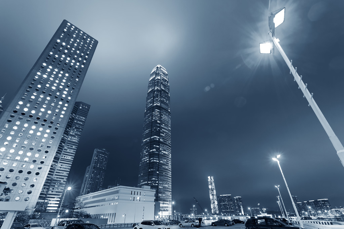
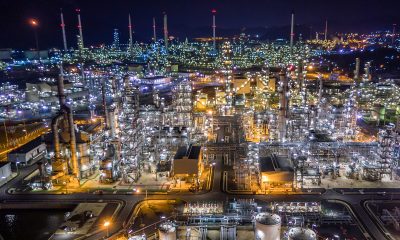
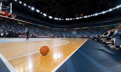
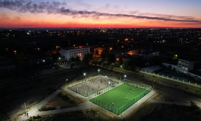
High power LED flood lights (100W to 500W) are designed to deliver a substantial amount of lumens for area, roadway, task, or accent lighting. This versatile family of outdoor luminaires finds an array of applications that require directional illumination over a defined zone, whether to spotlight a point of interest with a strongly focused beam of light, or to evenly illuminate large areas or vertical surfaces with intense white light. These luminaires can be used as a raised source of light to illuminate specific geometric areas, such as parking lots, airports, freight terminals, highway interchanges, sports grounds, golf courses, toll plazas, industrial sites, and outdoor storage areas. Hight power LED flood lights are also used to accentuate and highlight architectural elements such as façades, monuments, columns, and iconic structures. Flood lights are aimable, which, along with proper beam design, locations and mounting heights, contributes to a very effective yet flexible outdoor lighting solution.
The cons of metal halide lights
LED flood lights are created to outperform conventional fixtures which are power hungry and maintenance heavy. In the past, high lumen output floodlighting applications were dominated by metal halide lamps. While metal halide lamps offer up to 20 times the lamp life and four times the efficiency over incandescent lamps and are available in very high wattages (up to 2,000 Watts), they can present a number of concerns.
- These lamps operate at higher temperatures (900 to 1,100°C) and high pressures (520 to 3,100 kPa). At the end of life, they are subject to non-passive failure which may pose fire hazards.
- While lower wattage bulbs may last as long as 20,000 hours, higher wattage bulbs, such as the 1500 W bulbs commonly found in stadium fixtures, typically have a drastically shortened bulb life in 3,000-hour range.
- The long start-up and hot restrike time as well as the shorten lifespan under frequent on/off switching operation make it impossible to exploit the energy savings potential of lighting controls with metal halide systems.
- Another concern with using metal halide flood lights is high optical losses. A metal halide lamp casts its lumen output in all directions, which results in a low light extraction efficiency.
- High wattage lamps often require large and complex optical devices to capture and distribute light, which not only adds cost and size to the luminaire but also increases wind loading and weight.
LED lighting opens up a world of opportunities
Over the past decade, floodlighting technology has seen a monumental shift from HID to LED. The radical transformation is fueled by a suite of compelling benefits offered by LED lighting. The luminous efficacy of LEDs has surpassed previous lighting technologies to exceed 200 lm/W and still has significant room to improve. The remarkable improvement in light source efficiency is not the only killing advantage of LED lighting. The opportunity to yield greater energy savings beyond just improvements to light source efficiency is more breathtaking. With LED lighting, different aspects of lighting application efficiency (LAE), which include optical delivery efficiency, spectral efficiency and intensity effectiveness, can be considered and co-optimized for different applications.
The unique physical and optical characteristics of LEDs allow more effective delivery of the light to the target. With precision engineered optics, more than 90% of the light emitted by the LEDs can be extracted out of the luminaire and precisely distributed to a defined target. In comparison, more than 30% of the light produced by a metal halide lamp is lost within the fixture and not all light that escapes from the fixture is delivered in a direction that is useful for the intended application.
An array of LEDs can be arranged to form a surface emission device which, in combination with package-scale optical control, delivers precisely controllable distributions with high illuminance uniformity for improved quality of lighting and minimized installations of luminaires. With full, instantaneous dimmability and the ability to endure frequent on/off switching operations, LED flood lights can be controlled to deliver the right amount of light on demand, thereby driving down energy usage. LED lighting offers the new capability of precisely controlling the spectral power distribution (SPD), which allows for prescribing color quality that maximizes the LER and visual performance.
While energy savings deliver an immediate benefit, a significant part of ROI (return on investment) from the use of LED flood lights is due to reduced maintenance costs. Maintenance costs for HID lighting can quickly add up when accounting for the expenses in replacement lamps, labor and equipment, whereas LED technology offers the chance to create lighting systems that are virtually maintenance-free during the rated service life of numerous years or tens of thousands of hours.
Design and configuration
Hight power LED flood lights are complex systems because their thermal, optical, and electrical operations are interdependent. A set of system components must work in unison to form an integrated whole that ensures the LEDs perform to their full capacity under the optimally controlled conditions of the operating environment. The system into which the LED packages are assembled to provide mechanical strength, thermal management, optical control, power supply, and environmental protection has a significant impact on unlocking the full performance potential of the LEDs and the value of the luminaire for a particular application.
A high power LED flood light is either a fully integrated system or a modular assembly. A fully integrated LED flood light has a single light engine and the design of other components is dedicated to serving the needs of the light engine. A modular LED flood light is comprised of multiple LED modules. These modules are self-contained light engines that incorporate all functional components but the driver circuit. The integrated design is typically used in systems with a wattage rating of less than 300W. The modular design provides high flexibility in luminaire configurations as well as system scalability for construction of higher wattage LED flood lights.
Light source
In current LED technology employed for floodlighting applications, white light is generated by phosphor converted LEDs which combine an InGaN-based blue LED with a phosphor down-converter. Phosphor converted LEDs are packaged using different technology platforms, which leads to varied performance characteristics based on materials of construction, package architecture and manufacturing processes. The most impacted performance characteristics of LEDs related to the use of different package platforms are luminous efficacy, lumen depreciation and chromaticity point stability.
While mid-power LEDs have a better luminous efficacy than other types of LEDs, they have the least resistance to lumen depreciation and color shift. The plastic resin that is used to construct the reflective housing is prone to thermal and photo degradation. While chip-on-board (COB) LEDs have improved thermal stability as a result of assembling LED chips onto a ceramic substrate or metal‑core printed circuit board (MCPCB), the high density array of LED chips can produce an excessive amount of heat that may overwhelm the thermal path and introduce a high thermal stress to the phosphors.
The fundamental packaging philosophy of ceramic based high power LEDs and chip-scale package (CSP) LEDs provides a high efficiency thermal path to extract heat from the active region of the LED. These LEDs exhibit excellent lumen maintenance even at high operating temperatures and drive currents.
An LED can be characterized as having a particular SPD, which defines its color rendering performance and correlated color temperature (CCT). The spectral behavior of an LED depends on the composition of the phosphor down-converter. The trade-off between color quality and luminous efficacy has remained. The LED package selection in this regard will sway in different direction depending on the application requirements.
Thermal management
Thermal management remains a ubiquitous challenge for high power LED lighting systems. In general, LEDs dissipate more than 50% of the electrical input power as heat at the semiconductor die. InGaN-based white LEDs exhibit an efficiency droop at high drive currents. The higher the drive current is the higher the percentage of electrical power is converted to heat. Furthermore, phosphor down-conversion to transform shorter wavelength (blue) into longer wavelength (yellow) within the high flux density LED package produces a significant amount of Stokes heat.
Heat must be moved away from the LED package at a rate that exceeds the rate the waste is being generated. Heat accumulation will overheat the LED package, eventually leading to lumen depreciation and device failure due to phosphor and package material degradation as well as increased crystal defect formations and growth of threading dislocations in the active region of the diode.
The goal of thermal management is to ensure that the temperature of the LEDs and other temperature-sensitive components is maintained within functional and absolute maximum limits. To effectively cool the self-heating semiconductor devices, the thermal resistance of all the components along the thermal path between the LED junction and ambient air must be minimized and the heat sink must provide an adequate capacity to absorb the heat and then to convect it away to the ambient air. The efficient transfer of waste heat by thermal conduction from the LED junction to the heat sink involves the formation of higher reliability, high thermal conduction capacity solder joints (or solder-free interconnects), and the use of low thermal resistance MCPCBs and thermal interface materials.
To facilitate heat dissipation, the heat sink and housing of an LED flood light are typically formed as one piece and are constructed from low copper aluminum alloy using the extrusion, cold forging, or die casting process. A passive heat sink commonly comprises an aerodynamically designed structure of greater physical volume, which simultaneously maximizes the effective surface area and the convection heat transfer coefficient.
Driver and control circuitry
The critical part that defines the lifespan and performance of a high power LED flood light is the driver. While linear power supplies bring an attractive reduction in cost and complexity, most LED drivers that are used to operate high power LED systems are designed as switching power supplies. The associated costs for such LED drivers are relatively high, but this disadvantage is significantly outweighed by the drivers’ ability to provide higher efficiency power conversion, better quality output, and more robust protection of the LEDs against abnormal operating conditions. In addition to the main AC-DC power conversion, an SMPS LED driver performs many sub-tasks sequentially or in parallel. These sub-tasks include harmonic reduction and power factor correction, electromagnetic interference (EMI) screening and filtering, galvanic isolation between primary and secondary, drive current regulation, dimming control, protection against overvoltage, short circuit, overload, and overtemperature faults.
Typically, the LED drivers implement a two-stage topology. An LED driver that includes an active PFC stage followed by a DC-DC converter stage provides a substantially constant current to the load with a high circuit efficiency, while enabling high voltage operation and ultra-wide input voltage ranges (e.g., 120–277 VAC, 347-480 VAC,120-480 VAC, 90-528 VAC) and providing high immunity for the connected LED modules. (In areas with a high lightning strike density, it’s still necessary to add an external surge protector device.) In contrast, single-stage LED drivers face many limitations in high-power applications, which include low converter efficiency, narrow operating voltages, a high EMI signature, increased size and cost of the surge protection components, narrow dimming range, and high output current ripple (flicker) characteristics.
Where dimming will be required as part of any control strategy, the driver may be configured to support output current regulation through constant-current reduction (CCR) and/or pulse-width modulation (PWM). It may accept control input through an analog interface (1-10VDC) or a digital interface (DALI, ZigBee, Z-Wave, etc.).
Light distribution
Hight power LED flood lights are generally direct lighting systems that distribute all the emitted light in the general direction of the surface to be illuminated. These luminaires are available in symmetric and asymmetric beam patterns, with light distributions ranging from tight spot to wide flood. The light distribution of an aimable luminaire is typically described with beam spread based on the luminaire’s field angle degrees. The beam spreads are often classified into the NEMA beam types from 1 to 7 with tighter beams having lower beam type numbers and the wider beams having higher numbers.
The directional nature of LEDs allows them to eliminate the use of secondary optics in some area and flood lighting applications. However, most applications require the use of specialized optics to regulate luminous flux from the light source into a controlled beam. Optical control for LED flood lights is usually accomplished with reflectors or lenses. Since LEDs afford an opportunity to extract their luminous flux directly from the source, the secondary optics are typically designed as package-scale optical systems. A very common design of floodlight optics makes use of total internal reflection (TIR).
TIR optics can produce smooth circular beams with full width at half maximum (FWHM) angular widths as narrow as 10° and an optical efficiency as high as 92%. However, TIR optics are usually molded from plastics which have limited thermal stability. They may be thermally stressed by the self-heating high power LEDs of which the phosphor down-converter temperatures can approach 150° C. When a lighting system places high demands on the thermal stability of its optics, precision engineered aluminum reflector system could be a more appropriate choice.
Combatting environmentally-induced failures
Outdoor luminaires are continuously exposed to harsh environments and extreme weather conditions. Exercising tight control of environmental conditions for a high power LED flood light is as important as thermal management, optical engineering and drive current regulation. It is a required practice to holistically seal the luminaires at all points of entry and material transition to protect the lighting system from dust ingress and rain/water invasion from any direction. The optical assembly should be protected by a tempered glass lens which also facilitates dust shedding. During changing environmental conditions or temperature changes within the lighting system, pressure (which puts stress on seals) and condensation (which clouds lenses) can build inside a sealed optical enclosure. Installing a membrane vent in the sealed enclosure enables pressure equalization and removal of condensation. A chemical conversion coat and protective powder coat finish lend corrosion resistance to the aluminum housing.
The luminaires should be constructed with excellent resistance to mechanical impacts such as shock and vibration. Careful consideration should be given to the reliability of the solder joint between the LED package and MCPCB under the influence of mechanical impacts.


Loading...