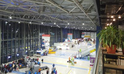
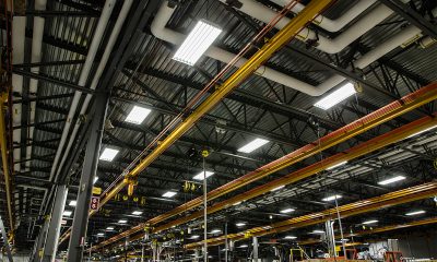
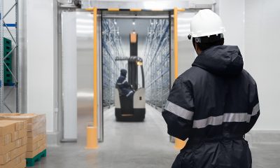
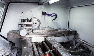
High bay lights often experience extremes in temperature conditions
A high operating temperature capable LED luminaire is designed for use in industrial applications that involve high-temperature materials processing or thermal energy generation. In many industries the production process necessitates process heating (treatment at elevated temperatures) to affect solids and liquids heat-up, melting and evaporation or to facilitate reaction mechanisms. Such processes include agglomeration and sintering, calcining, curing, drying, fluid heating, forming, heating and melting, heat treating, metal reheating, smelting, incineration/thermal oxidation, etc. Process heating is used in a vast range of industrial applications, which encompass the manufacturing of advanced ceramics and specialty metals, the production of construction materials (such as cement and wallboard), the recovery of lime in the kraft process of the pulp and paper industry, the application of coatings to metallic and nonmetallic materials (including ceramics and glass), the production of anodes from petroleum coke for aluminum smelting, the extrusion of rubber and plastics, the conversion of iron into steel, the production of metal castings, the hot-shaping of glass and plastic thermoforming, the tempering and annealing of glass and ceramics products, the catalytic steam reforming of hydrocarbons to produce hydrogen and other gases (for the synthesis of ammonia, methanol, etc.), the thermal cracking of hydrocarbons for the production of ethylene, the drying of textiles and polymers, baking, roasting and frying of food, etc.
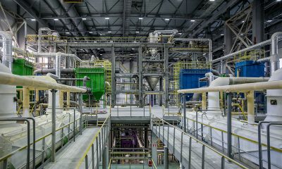
Ambient temperatures in facilities with process heating equipment
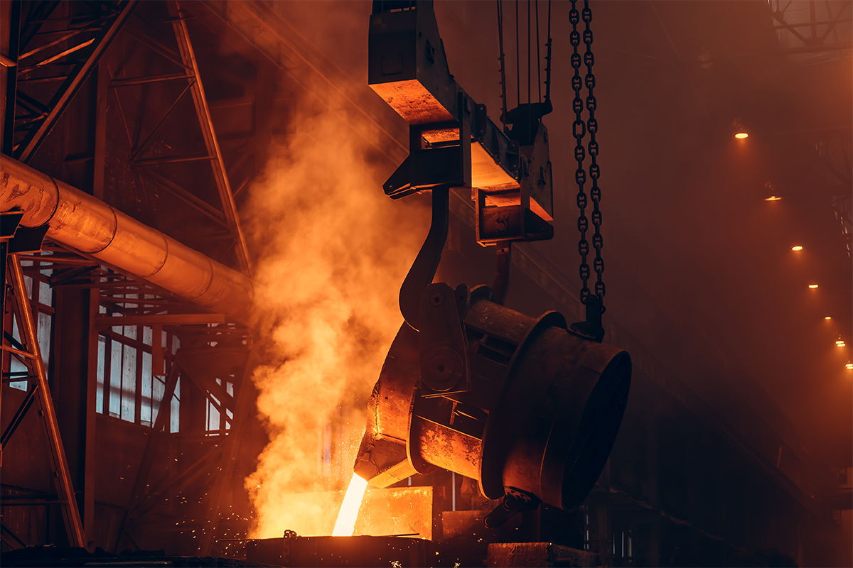
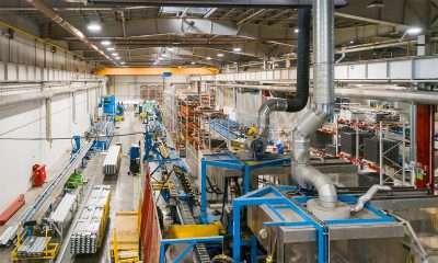
The radiant thermal energy from process heating equipment installed in many industrial workplaces ends up in environments with abnormally high ambient temperatures. Steel mills, for example, use coke ovens and blast furnaces for ironmaking, basic oxygen furnaces for steelmaking, and reheat furnaces for continuous casting. The mean radiant temperature (MRT) in these environments is often greater than 60°C (140°F) and thus leads to a very high ambient temperature.
It’s not uncommon for industrial facilities with process heating equipment to produce extremely hot environments with the ambient temperature in the range of 40° to 65°C (104°-149°F) or even higher. High ambient temperatures make it difficult for light fixtures to shed heat, which is required to maintain appropriate operating criteria. Standard lighting products designed to be operated under room temperatures will not survive in such conditions. The need of creating optimum visual conditions for quality control, productivity and safety places high demands on the robustness of light fixtures, which must withstand the demanding conditions of a high ambient temperature environment.
LED performance and lifespan are temperature-dependent
LED lighting has become the dominant technology across all lighting applications. The technology is favored for its practical potential of delivering exceptional levels of energy efficiency, reliability and durability along with high quality illumination and new control capabilities. Nevertheless, LED lighting products are challenged by their negative temperature coefficient of performance and lifespan. Two critical components of an LED luminaire—the LEDs and driver—are temperature-sensitive. That is, higher temperatures accelerate the kinetics of the failure mechanisms of these components.
In abnormally high ambient temperature environments, this disadvantage of LED lighting can be amplified. As a result, thermal management has taken center stage in implementation of LED technology in lighting applications. The primary goal of thermal management for an LED lighting system is to build a low resistance thermal path so that the heat generated within the LED packages can be effectively transferred to the ambient atmosphere. The thermal transfer path must be adequately dimensioned to handle the applied power load. Vice versa, the drive current should be controlled to ensure the amount of heat introduced to the semiconductor junction as a result of power dissipation will not overwhelm the thermal path.
Thermal management
In general, thermal management of LED luminaires revolves around two controllable factors that affect the junction temperature of an LED—building a robust thermal path and exercising tight control of the drive current. However, the ability of an LED thermal management system to dissipate heat is highly dependent on a third variant—ambient temperature. Give the high efficiency of a thermal path, the rate at which heat is transferred through the thermal path is ultimately determined by the temperature differential, or gradient, between the heat source and surrounding ambient air.
As thermal energy flows from the higher temperature to the lower temperature region, a high ambient temperature environment creates high resistance which impedes heat flow and significantly reduces the overall effectiveness of the thermal management system. In industrial environments with elevated ambient temperatures, an adequate path to thermal conduction and convection for the heat source is not adequate for failure-free operation of an LED luminaire over a meaningful life. It is necessary to take into the account the high temperature performance of the LEDs and other sub-systems of the luminaire that may incorporate temperature sensitive components.
The importance of LED package platform
The ability for the LEDs to thrive in a high ambient temperature environment depends on the package platform, chip fabrication technology and down-converter materials they use. Leadframe LED packages are obviously not a choice for high temperature applications as the thermal resin that’s used for molding the reflective package housing degrades at an elevated temperature. These plastic LED packages are designed to operate at a junction temperature that does not exceed 85°C, whereas in industrial environments such as steel mills, ceramics firing workshops and glass manufacturing facilities the high ambient temperature and the high-lumen-output operation requirement usually push the LEDs to operate at junction temperatures above 120°C.
The challenging environment calls for the use of LEDs with less temperature-dependent failure mechanisms. Only LED packages that are absent of plastic substrates should be considered for heat resistant lighting applications. High power LEDs which are built on ceramic substrates and the package-free chip scale LED packages (CSP LEDs) provide excellent resistance to thermal degradation. The removal of the reflective plastic housing allows these packages to survive significantly higher operating temperatures. The device architecture, which involves electrical interconnectivity (anodes and cathodes), current spreading, thermal path and die attachment, lends them the ability to handle high thermal and electrical loads.
Substrate technology defines the upper limit of LED thermal performance
Aside from the package platform, the chip fabrication technology and down-converter material can make a big difference in LED’s thermal performance. At elevated temperatures, both the wall-plug efficiency (WPE) of the LED chip and the phosphor conversion efficiency (PCE) of the down-converter layer will be reduced. While efficiency degradation can generally be tolerated in applications with abnormal operating conditions, temperature-induced failure mechanisms can lead to a shortened lifespan. High operating temperatures can accelerate atomic defect generation within the active region of an LED chip.
Most GaN LEDs are based on heteroepitaxial growth where growth is initiated on a substrate other than GaN. Heteroepitaxial growth of GaN is usually performed on an inhomogeneous substrate leads to defects in the crystalline structure known as thread dislocations. High thermal stresses can speed up nucleation and growth of dislocations, which eventually causes the premature failure of the LEDs. Threading dislocations form in highest densities on GaN LEDs grown on the sapphire (Al2O3) substrate (13% lattice mismatch with GaN). Because of the low material and manufacturing costs most high power LEDs are of the GaN-on-Sapphire type. Silicon carbide (SiC) was introduced as an alternative for sapphire substrate. Compared to a sapphire substrate, a SiC substrate creates fewer dislocations (3.4% lattice mismatch with GaN). Fewer dislocations with the GaN-on-SiC technology not only contributes to a 5 to 10% efficacy increase over chips with a sapphire substrate, but also allow the LEDs to perform more reliably at high junction temperatures.
High power LEDs offered by Cree, who championed the use of SiC substrates for LED fabrication, are arguably the best products currently available on the market. These products can operate at a junction temperature as high as 150 °C, with significantly better lumen maintenance than the competitor’s products. High power LEDs can also be fabricated using GaN-on-GaN and CSP technologies, which are theoretically superior to the GaN-on-Sapphire and GaN-on-SiC counterparts.
Thermal degradation of the phosphor down-converter in LED packages can have one of the most significant contributions to catastrophic failures of LEDs. The phosphor conversion process can lead to phosphor temperatures 30° to 50° C above the junction temperature of the LED due to Stokes loss and imperfect quantum yield. The use of high operating temperature capable phosphor down-converters is required to prevent phosphor thermal degradation, carbonization of the encapsulant, and delamination/cracking at the phosphor-binder interface.
Electrolytic capacitor
The progresses made in chip fabrication and device packaging have allowed LED manufacturers to produce LEDs that stand up to the test of thermally challenging conditions. LEDs no longer get in the way of creating heat resistant lighting systems. The industry leader Cree has products with an L90 life of 40,000+ hours or an L80 life of 60,000+ hours rated for operating environments with the in-situ ambient temperature maintained at 105°C.
The critical part that defines the lifespan of LED lights for use in high ambient temperature environments is the driver. Specifically, the electrolytic capacitor that is almost exclusively used in mainstream commercial SMPS-based LED drivers is considered as the weakest component in LED drivers. It has been a long-time debate whether LED drivers containing electrolytic capacitors can match the long lifetime of the LEDs.
While the removal of electrolytic capacitors has been explored ever since the commercialization of LED lighting technology, there are no replacement components that have the volumetric efficiency, voltage and temperature rating, and cost-effectiveness comparable to electrolytic capacitors. The large capacitance value of electrolytic capacitors makes them the most effective components for energy storage, ripple voltage filtering, and DC voltage smoothing. The downsides of using electrolytic capacitors is that they can explosively fail if the electrolyte overheats and starts to evaporate. The loss of electrolyte causes the fall of capacitance and an increase in equivalent series resistance (ESR), which can reduce drive efficiency, cause LED to flicker and experience high electrical stresses due to an increase in the output voltage ripple. The failure of electrolytic capacitors can even lead to malfunction or no-start conditions of the control circuits. The electrolyte loss has strong temperature dependency. Every 10°C in the operating temperature the life of the electrolytic capacitor is reduced by a factor of 2.
As with the LEDs, the temperature-dependent degradation mechanism of electrolytic capacitors doesn’t necessarily mean that they cannot survive high ambient temperature conditions. Electrolytic capacitors are available with rated life up to 12,000 hours at 105 °C (ambient temperature). Leading power supply manufacturers such as Mean Well use electrolytic capacitors rated with a life of 10,000 hours @105 ℃. When LED drivers are operated at a high ambient temperature of 70 °C the electrolytic capacitors contained therein will have a theoretical lifespan of more than 80,000 hours.
The challenge lies in the thermal management of the electrolytic capacitor. The operating temperature of a capacitor is a function of the case temperature of the capacitor, and the internal heating within the capacitor caused by the ripple current flowing through it. To achieve a lifespan that approaches the theoretical value of an electrolytic capacitor, the case temperature and internal resistance (ESR) should be reduced to a minimum. The case temperature of the capacitor depends on the ambient temperature, the power dissipated by the driver, and possible thermal stresses from the LED light engine.
Efforts must be made to reduce the temperature increase caused by driver power dissipation and LED thermal load. The more efficient a driver is, the less the amount of power will be dissipated as heat by the driver circuit. Complete thermal isolation between the driver and light engine must be implemented. Failure to address these requirements can cause a significant increase in the case temperature of the capacitor.
Power conversion in SMPS LED drivers
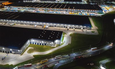
The circuit efficiency of the driver and the capacitor’s internal heating due to ripple current all depend on how the LED driver is designed. Most LED luminaires installed in high ambient temperature locations have a high lumen output which is intended for high bay applications while allowing the luminaires to be mounted away from thermal radiation of process heating equipment. At higher power levels, the driver topology can make a huge impact on the circuit efficiency, output quality and driver reliability.
While single-stage LED drivers are more cost competitive than two-stage LED drivers due to the reduced part count, they face challenges that limit their usability and value for high power applications. Achieving very high efficiency at higher power ratings can be particularly challenging for single-stage topologies. For high wattage systems, low efficiency power conversion not only means a huge energy waste, but also results in generation of a tremendous amount of heat within the driver circuit. The single stage topology requires the use of very big output capacitors to eliminate the resultant 100/120 Hz output ripple. Smoothing large AC ripple to a narrow magnitude can severely increase the workload of the electrolytic capacitor, which in turn intensifies internal heating.
The two-stage LED driver has a dedicated PFC stage that uses a capacitor as the line-frequency energy buffer and a DC-DC converter stage that uses capacitor to filter out the output current ripple. The two-stage design minimizes stresses on the electrolytic capacitors and enables higher efficiency power conversion in high wattage systems, which translates to a lower total internal thermal load when compared with the single-stage design.
Driver-on-board (DOB)
With effective thermal management, a thoughtfully designed two-stage LED driver that use electrolytic capacitors can last as long as 60,000 hours at the 70°C ambient temperature. This level of robustness allows for applications in the majority of high temperature environments. For installations in environments with extremely high ambient temperatures, remote driver solutions or driver solutions that eliminate the use of electrolytic capacitors should be considered.
Where it is possible, the use of high efficiency two-stage SMPS LED drivers should take precedence over other solutions. So-called “driverless” LED lights are claimed to have high operating temperature capability. However, they’re not really driverless. These luminaires are operated by linear power supplies which can work in absence of electrolytic capacitors. The linear regulator is very simple and its use of solid state components allows for driver-on-board (DOB) design.
While “driverless” LED lights seem to eliminate the weakest link of a conventional LED driver, they have a very narrow range of operating voltages and provide minimal downstream components protection. This lends them unreliable in industrial applications where dirty power is often present. Linear power supplies regulate the LED load by throwing away excess power, which can produce an additional thermal load to stress the co-located LEDs in a DOB or “driverless” LED light.
Secondary optics
The thermal stability of secondary optics should enter into the design considerations as well. Many LED luminaires use lens arrays injection molded from acrylic or polycarbonate for high efficiency optical control. The close proximity installation to the self-heating LEDs can raise their operating temperature. In hot environments their reliability is seriously challenged. The use of acrylic lenses should be excluded because of their poor thermal stability. Polycarbonate lenses have better thermal performance but are not recommended for applications where the operating temperature can rise above 110°C. A safer solution would be to use silicon lenses, glass lenses, or aluminum reflectors.


Loading...