General description
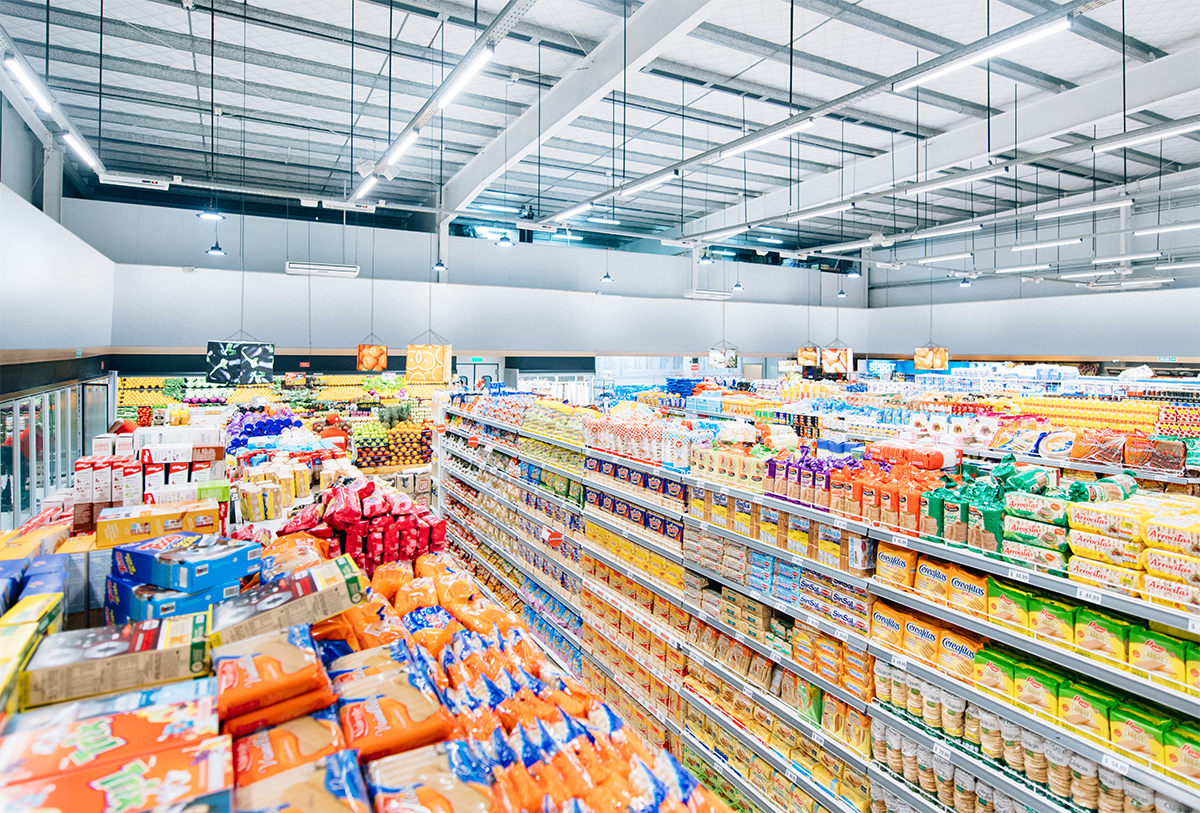
LED tube lights are direct replacements for linear fluorescent lamps. They are designed specifically to retrofit existing fluorescent fixtures that can take the form of troffers, shop lights, wraparounds, linear strips, linear high bays, and vapor tight fixtures. Throughout the world, luminaires that incorporate linear fluorescent lamps had been ubiquitous in commercial facilities and industrial spaces which include shopping centers, retail buildings, office buildings, educational facilities, hospitals, logistics centers, warehouses, etc. High energy and maintenance costs are a particular burden to facilities with their lighting infrastructure based on legacy technologies. As energy codes are prescribing ever lower allowances for power consumption and the global call for carbon reduction grows ever louder, technology upgrading is seen as a prime mechanism to address challenges. Tubular LED (TLED) lights are products designed to facilitate a rapid and safe conversion from fluorescent to LED technology, allowing for immediate energy savings and performance improvements.
LED retrofit lamp
LED tube lights are a major category of LED retrofit lamps. Retrofit is a lighting upgrade method that involves replacing the existing light sources with more advanced technologies, while making use of the original luminaire housing, following the original light distribution pattern, and performing no or minimal modification to existing wiring or sockets. A lighting upgrade can also be made through redesign, which requires new fixtures with an entirely new light distribution pattern. Retrofitting the existing luminaires is a more commonly adopted approach to lighting upgrade. It not only reduces material cost, but also saves a lot on labor costs which often equal or exceed the costs of lighting equipment when the upgrading process involves relocating and installing new luminaries and new circuits. LED retrofit lamps are simple, cost effective to install. With the physical configuration, electrical characteristics and photometric performance matched to those of legacy light sources, they can be easily installed into the existing fixtures and work correctly therein.
T8 LED tube
In most instances, an LED tube light refers to a T8 fluorescent lamp replacement. The T8 lamp measures 8/8ths (1) inch or 2.54 cm in diameter. This family of products are available in imperial lengths of 2-foot, 3-foot, 4-foot, 5-foot and 8-foot linear lamps. The metric lengths of these linear lamps include 600 mm, 900 mm, 1200 mm, 1500 mm, and 1800 mm. T8 lamps are fitted with G13 medium bi-pin bases which are also used by T12 lamps. T8 LED tube lights reproduce the form factor of T8 fluorescent lamps and use G13 lamp bases as well. Since the T8 lamp and the corresponding T12 lamp are of the same length and supplied with the same bases, a T8 LED tube light can replace a T12 fluorescent lamp of the same length. T8 lamps are not interchangeable with T5 tubular lamps which are 5/8ths inch or 1.6 cm in diameter, use G5 miniature bi-pin bases, and have a shorter maximum overall length (approx. 2″ shorter). T8 LED tubes with a 4-foot length have a comparatively high volume. Products in other lengths, in particular the longer versions, are far less commoditized than the 4-foot LED tubes.
Every fluorescent fixture feeds power through a ballast
There is a fundamental tradeoff between the labor cost and ease of installation when it comes to the choice of a TLED retrofit solution. Furthermore, this choice may result in safety concerns and has a profound impact on the product efficiency and lifespan. These complications have to do with the ballast, which regulates AC mains power to achieve suitable voltage, current and waveform for starting and operating the lamp. Fluorescent ballasts vary considerably in circuit design and complexity. They can be divided into two types: magnetic and electronic. Since magnetic ballasts are very inefficient and more likely to produce flicker and stroboscopic effects, they were not used much anymore after the introduction of electronic ballasts which overcome many of the problems encountered with magnetic ballasts. A magnetic ballast employs the principle of magnetic induction to regulate power to a fluorescent lamp. Electronic ballasts use semiconductors instead of magnetic coils to regulate starting voltage and to maintain proper operating current. They are distinguished by method by which the lamp is started. An instant start (IS) ballast initiates the discharge arc using a relatively high voltage. A rapid start (RS) preheats a filament for the electrode pins in order to assist with lamp starting. A programmed start (PS) ballast is an improvement on the rapid start ballast. Precise heating of lamp filaments and control the pre-heat time result in reduced thermal shock on the cathodes, which extends the lamp life under any switching frequency. PS ballasts, however, are the most expensive. This caused them to lose popularity to IS ballasts, which are of a lower cost and provide maximum energy savings despite their short lifespans in situations where the lamps are frequently cycled on and off.
Bypass the ballast or operate on it
The ballast is physically located external to the lamp and assembled with the luminaire housing. This configuration poses a tough dilemma: to feed the LED load with power supplied by the fluorescent ballast or to bypass the fluorescent ballast and direct wire to the tombstone? A simple swap of the existing linear fluorescent lamp (LFL) with an LED replacement lamp and allowing the LED tubes to run off the existing fluorescent ballast bring plug-and-play simplicity to lighting upgrade. The price to pay for this simplicity, however, is a lower efficiency and uncertainties arising from the incompatibilities between the fluorescent ballast and LED driver. Ballast bypass installation requires electrical and/or structural modification to the existing LFL fixture in order to connect the LED driver to mains power. The advantage of bypassing the ballast is that there will be no power loss and failure points associated with the use of the ballast. However, the installation is necessarily to be carried out by a qualified electrician, which means a higher upfront cost.
Types of T8 LED tube lights
In retrofitting fluorescent fixtures with LED tubes, it is important to weigh benefits against costs of different options. Depending on the configuration, LED tube lights can be classified into four types: Type A (Ballast Compatible), Type B (Ballast Bypass), Type C (External Driver), and Dual Mode (Type A + Type B).
Type A (ballast compatible)
Type A LED tube lights are integrated systems that operate off of the existing fluorescent ballasts in LFL fixtures. The internal LED driver must be designed to work correctly with the fluorescent ballast; hence the Type A LED tube is also known as a ballast compatible LED tube. A retrofit is carried out by removing the LFL and replacing it with the LED tube, without any extra effort or re-wiring. This retrofit solution works straight out of the box. However, with the convenience comes some limitations. A ballast compatible LED tube suffers from the additional power loss from the existing ballast. Its dimming and control capabilities are inherently limited. The ballast can fail before the LED tube reaches its end life. It is also important to verify that the LED driver can operate on the particular ballast in the fixture. Not all LED tubes have the compatibility with any type of ballasts.
Type B (ballast bypass)
Type B LED tube lights operate with an internal driver that is powered directly from the main voltage. In this configuration the ballast is simply disconnected and the line voltage is directly brought to the sockets. Since the ballast is bypassed and the LED tube runs directly off of line voltage, there are no compatibility issues, power loss, premature failures and maintenance costs resulting from the use of ballasts. The internal wiring and in some cases the sockets in the LFL fixture must be modified. Labor costs thus become an important factor in accessing the ROI and payback. Electrical safety is a concern with ballast bypassing operation. Type B LED tubes are either single- or double-ended. A single-end LED tube accepts main power on one end while the other end becomes a dummy end. A double-end LED tube accepts main power on both ends. The single-end LED tube is generally preferable to the double-end counterpart because there is no shock hazard with this configuration. Unless safety switches are installed to prevent electric power from flowing through the lamp before socket engagement of both ends, retrofitting fluorescent fixtures with double-end LED tubes can potentially expose the installer to the mains voltage during installation.
Type C (external driver)
Type C LED tube lights operate on external LED drivers, in a way physically similar to linear fluorescent lamps which are powered by ballasts outside the glass tube. This configuration requires electrical modification to the existing fixture. The sockets are wired with low voltage DC which is provided by the LED driver. The LED driver is mounted somewhere in the fixture and mains powered by connecting to the fixture input wires. The LED driver may also wire directly to the LED load via dedicated wires and the sockets are merely used as mechanical supports. While Type C involves the most labor-intensive modification, it is the safest retrofit configuration for installers and the easiest configuration to troubleshoot and maintain. But more than that, this configuration allows to unlock the full potential of LED lighting. Without physical and wiring constraints, the LED driver affords the integration of high performance conversion, dimming and control circuits. The capacity of the remote-mounted LED driver can also be expanded to operate multiple T8 LED tubes for a fixture. Since the driver is located outside the lamp, the heat from the LEDs will not thermally stress the driver circuit or vice versa.
Dual mode (type A + type B)
Dual mode LED tube lights are designed for both ballast-connected (Type A) and ballast bypassing (Type B) operations. The internal LED driver automatically adapts to either ballast-regulated power or AC line voltage. While these hybrid systems can function both as plug-and-play and line-powered retrofit lamps, they do not make much sense. Dual mode LED tubes allow continued use after the ballasts fail, but the fixtures must be modified to bypass and remove the ballasts before the LED tubes can work as Type B systems. The high cost and complexity of these LED systems make it hard to justify their use in most retrofit applications. The challenges associated with both the Type A and Type B configurations need to be addressed. Electrical safety is a particular concern for a dual mode tube with double-end design.
Shunted and non-shunted Sockets
Care should be taken to avoid the incompatibility between an LED tube light and the existing lamp sockets. Type A LED tube lights should be designed to fit into either shunted sockets or non-shunted sockets. Retrofitting fluorescent fixtures with Type B LED tubes may necessitate replacing the shunted socket with a non-shunted socket or vice versa. The two pins of a shunted socket are electrically joined and the fluorescent fixture has a hot connection on one end of the lamp, and a neutral connection on the other. A non-shunted socket has separate pins to accommodate hot and neutral connections on the same end of the lamp. Typically, shunted sockets are found in fluorescent fixtures that use instant start ballasts and non-shunted sockets are found in fluorescent fixtures that use programmed start ballasts.
TLED design and construction
All LED tube lights except the Type C products are designed as integrated systems with the LED driver co-located within the tubular housing. The tubular housing may be a plastic tube, a glass tube, or a hybrid assembly of the aluminum/polycarbonate (ALU+PC) combination. Light is emitted from a linear LED module which is a metal-core printed circuit board (MCPCB) populated with an array of SMD LED packages.
In an LED tube with a full plastic or glass housing, the driver circuit is side-mounted in one of the end caps. In an ALU+PC LED tube, the driver circuit is inserted into the cavity of the D-shaped aluminum housing.
A pair of end caps provide mechanical support for an LED tube. Either all of the two end caps or one of them come with electrodes which connect to the power source. The end caps may be designed to allow rotation so that the beam can be easily directed where it is needed. The adjustable bases are mostly found in LED tubes with a narrower beam angle.
LED tubes do not spread light in all directions. Their beam angle ranges from 105° to 320°. Due to the very high directional intensity of LEDs, the selection of the optical lens must account for the tradeoff between glare control and optical efficiency. The optical lens of an LED tube light is offered in three finish options: clear, frosted (translucent) and opal (milky).
Tubular housing material and thermal management
LED tube lights are among the most commoditized LED products and the price has been falling precipitously. Today, the vast majority of the T8 LED tube lights take advantage of massive cost reductions from using full plastic or glass housings. When costs are cut the product performance suffers. The rate at which an LED package drops it luminous output is highly dependent on the temperature at the semiconductor junction. Thermal management is a significant concern for plastic and glass LED tubes. The low thermal conductivity of the housing material and the enclosed operating environment make the junction-to-ambient thermal resistance very high, which can result in significant reduction in the service life of the LEDs. To effectively dissipate thermal energy from the LED module, the thermal conduction and convection requirements must be fully addressed.
The ALU+PC construction provides a complete thermal path from the LED junction through the aluminum heat sink to the ambient environment. The aluminum extrusion can provide high efficiency thermal conduction to extract heat from the LED chip. Its surface area is maximized to ensure adequate thermal transfer to the ambient air through convection. With robust thermal conduction and convection working together to minimize thermal impedance, ALU+PC LED tubes dwarf glass and plastic tube with regards to lumen maintenance and color stability. Additional benefit with the ALU+PC construction is that it provides better bending resistance when compared with the plastic tube. However, extreme caution should be exercised to ensure that the aluminum housing is electrically isolated from the mains power circuit.
Light source
The mid-power LEDs used in LED tubes vary considerably in luminous efficacy, thermal performance and color quality. Plastic-molded lead frame LED packages still reign over the market due to their low cost and high luminous efficacy. These polymer-based LEDs contain one or two small InGaN dies mounted onto a metal-plated lead frame which sits in a polymer cavity and filled with phosphor mixed silicone. The cavity and lead frame are made reflective to minimize light absorption. The ability to effectively extract the photons generated lends the polymer-based LEDs a luminous efficacy way ahead of other types of LED packages. However, the polymer used to make the reflective cavity has limited thermal stability and photo resistance. Thermal degradation and photo-oxidation can lead to discoloration, which is the primary cause of chromaticity shift and lumen depreciation in the LEDs. Due to cost sensitivities, LED tube lights usually use LED packages made of thermally unstable polymers and operate fewer LEDs at higher drive currents to achieve the required lumen output for the application.
Unless otherwise specified, the spectral power distribution (SPD) of the LEDs is optimized for high efficacy operation, resulting in a compromise against color quality. A color rendering index (CRI) of 80 is often considered an acceptable value for applications with no special emphasis on color reproduction. The choice of correlated color temperature (CCT) may be dictated by the application requirement or governed by the efficacy requirement. With minimal Stokes losses, cool white LEDs offer a higher luminous efficacy than neutral and warm white LEDs. To provide uniform intensity and color across the linear emitting surface and multiple fixtures, the LEDs need to be sorted or binned with respect to chromaticity, lumen output, and forward voltage.
LED driver
The performance and lifetime of an LED tube light are heavily dependent on the configuration and electrical performance of the LED driver circuit which is an internal component of all LED tubes but Type C lamps. Typically, an LED driver used in an LED tube is a switching mode power supply (SMPS), containing multiple electrical circuits such as input power conditioning, AC/DC converter, power factor correction (PFC), DC-DC converter and output filtering circuits. They work together to ensure that the DC power delivered to the LED packages is appropriately regulated and controlled.
Single-stage topologies are more prevalent in low-power LED lighting applications than two-stage topologies primarily because of their higher conversion efficiency, lower cost, and smaller driver size. Nevertheless, single-stage LED drivers are usually less forgiving of surges and spikes than the two-stage counterparts. They tend to generate larger ripples in the output current, which can cause the LEDs to flicker and reduce their lifespan. The output side of these driver typically does not include galvanic isolation. In this case, reinforced insulation between the driver circuit and the housing must be provided to avoid electrical shock hazards.


Loading...