What is a T5 LED tube light
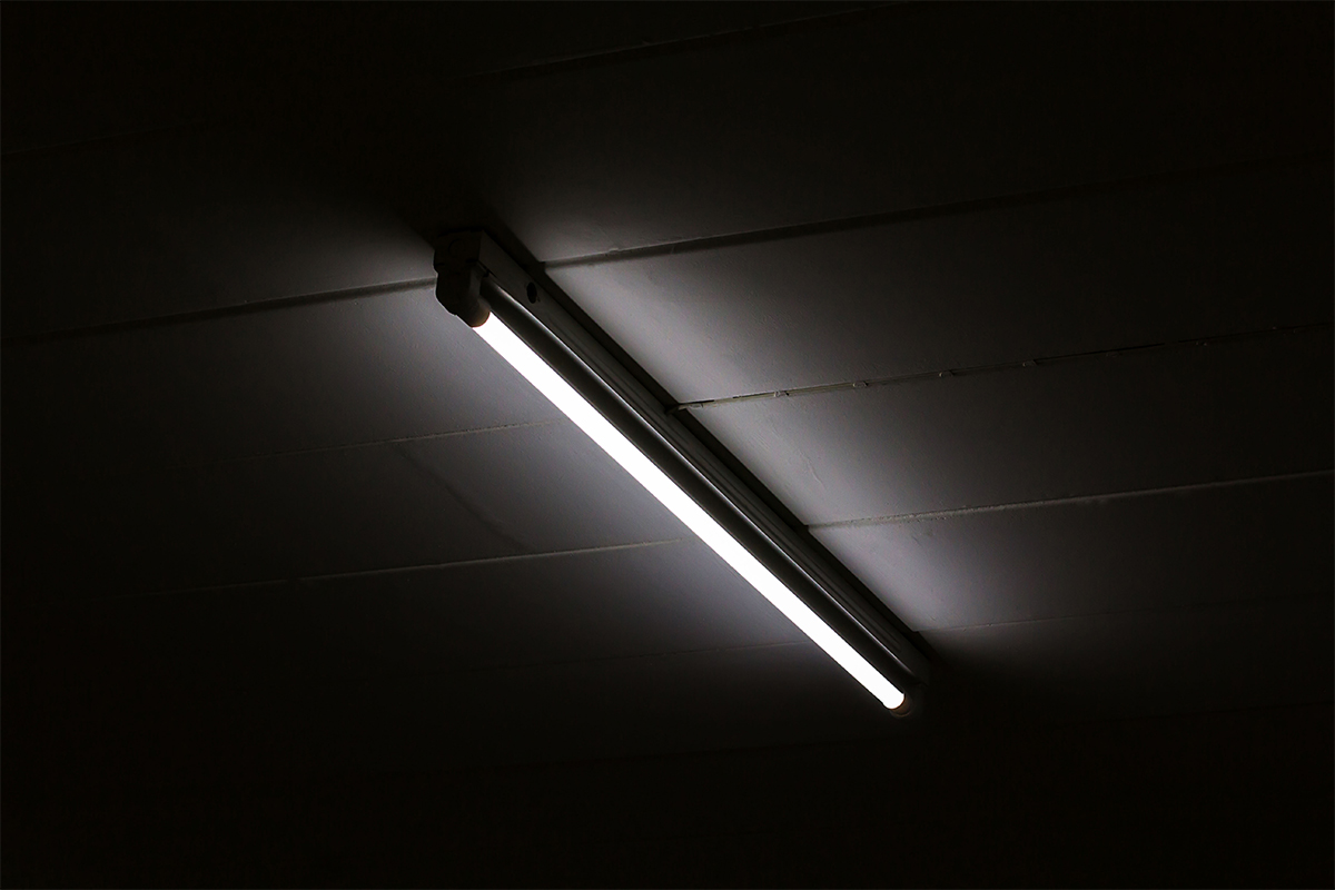
A T5 LED tube light is an LED retrofit lamp designed to replace the standard fluorescent T5 tube. With a slim profile and a lumen output comparable to T8 and T12 fluorescent lamps, T5 fluorescent lamps established its foothold in commercial, retail, residential, industrial and institutional lighting applications. In addition to the use in commercial ceiling lights such as troffers, high bays, shop lights and wraparounds, T5 lamps are used as the light source for indirect lighting systems, cabinet and shelf lights, and fixtures that illuminate small spaces. The world, however, is changing, and so do opportunities and challenges. With LED technology becoming a logical choice over other lighting options and all fluorescent fixtures being engaged in a bitter struggle to comply with ever-changing energy codes, upgrading all legacy systems with new technology is just around the corner. Retrofitting fluorescent fixtures with LED lamps is a simple, cost-effective solution to upgrading lighting. T5 LED tube lights offer an easy means to enhance the value of existing light fixtures by delivering high energy savings, lower maintenance costs and improved quality of light over lifetime.
T5 LED tube
In order for a T5 LED tube to replace, easily and operatively, a fluorescent lamp, it must first fit the physical configuration of the legacy light source. A T5 tubular lamp is 5/8ths inch or 1.6 cm in diameter. Electrical engagement with corresponding sockets of a T5 fluorescent light fixture is made using G5 miniature bi-pin bases. T5 LED tube lights are manufactured in lengths of 2-, 3-, 4- and 5-foot linear lamps, which are essentially equivalent to, but slightly longer than lamps in metric lengths of 600 mm, 900 mm, 1200 mm and 1500 mm. When it comes linear fluorescent lamps, T5 lamps are a world of their own. They cannot interchange with T8 lamps due to the use of different pin spacing on the bases as well as the shorter overall maximum lengths.
Lamp retrofit
By definition, a lamp retrofit is designed to reduce modification to the existing fixture to a minimum. Preferably the replacement lamp will support a plug-and-play retrofit. The uncertainty associated with a retrofitting project lies in electrical wiring. A T5 linear fluorescent lamp (LFL) is connected to an electrical ballast which is mounted in a metal or composite case somewhere in a fixture. The ballast provides the required electrical power to initiate an arc discharge and stabilizes the current flowing through the lamp.
T5 fluorescent lamps are primarily driven by programmed rapid-start electronic ballasts. A programmed-start ballast is an evolution of the rapid start ballast. A rapid start ballas applies the strike voltage and heats the two electrode pins (the cathodes) at the same time, whereas a programmed-start ballast heats the electrodes before applying arc power. This mode of operation results in extended lamp life and allows the lamp to survive high frequency on/off switching cycles. Basically, T5 lamps are driven with high frequency alternating current (AC) signals of high voltage with high peak voltages and also constant current with high peak currents. In contrast, LEDs are low voltage direct current (DC) devices. In order for the LED lamp to work correctly in an LFL fixture, some forethought and preparation are necessary.
Ballast! ballast! ballast!
The ballast is the X factor in developing a retrofit solution that involves conversion of linear fluorescent technology to LED technology. The difference in electrical characteristics between fluorescent lamps and LEDs distinguishes the configuration of an LED driver from that of a fluorescent ballast. As the electronic ballast outside the lamp supplies regulated power to the fluorescent lamp via two sockets, installing an LED tube directly into the existing sockets without rewiring makes the LED tube a part of the electrical circuit started by the ballast. The LED driver must be adapted to the output of the fluorescent ballast, which adds complexity to the driver design. On the other side, wiring the LED tube directly to AC mains power requires rewiring of the sockets to bypass the ballast. Thus, all retrofit solutions come at a cost and each of them demands the use of LED tubes with a particular driver configuration.
Types of T5 LED tube lights
Four driver configurations have evolved for retrofit applications. They are Type A (ballast compatible), Type B (ballast bypass), Type C (external driver), and Dual Mode (type A + type B).
Type A (ballast compatible)
Type A T5 LED tube lights operate directly from the fluorescent ballasts. The retrofit is just a simple swap of the existing fluorescent T5 tube with an LED tube of which the LED driver is configured to accommodate voltage and current regulated by a ballast. No rewiring is needed. It is the easiest way to retrofit a fluorescent fixture. The operational cost with this configuration is higher than that of an LED lamp operating directly from AC mains power because of the additional power conversion loss in the ballast circuit. What’s more, the malfunction of the ballast will result in a catastrophic failure of the entire lighting system.
Type B (ballast bypass)
Type B T5 LED tube lights run on AC mains power. This configuration involves electrical modification to the existing fixture in order to bring line voltage directly to the sockets. The installation requires rewiring to disconnect and bypass the ballast by a qualified electrician. Labor costs account for a decent portion of the upfront cost. The ballast removal leads to a higher system efficiency and reliability, which in turn gives a short payback on investment. Type B T5 LED tubes may be designed to run power through one or both ends. A single-ended circuit allows for safe installation. Double-ended T5 LED lamps must incorporate safety switches to provide shock hazard protection for the installer.
Type C (external driver)
Type C T5 LED tube lights are powered by external drivers. This configuration contrasts with Type A and Type B LED lamps that have an internal driver. The external LED driver is line powered and supplies low voltage DC power to the sockets or directly to the LED load. Type C is the most labor-intensive retrofit configuration; but there are big advantages. The LED tube and sockets are wired with low voltage power, which makes it safe to touch. The external installation eliminates constraints on the physical space and signal wiring, allowing the driver to use electrical circuits that provide higher efficiency and high reliability power conversion and to implement advanced dimming and control strategies. The remote-mounted LED driver can also be configured to drive multiple T5 LED tubes for a fixture.
Dual Mode (type A + type B)
Dual mode LED tube lights incorporate two wiring options (Type A and Type B) into a single system. The internal LED driver is ballast-compatible and can also run directly off of line voltage. The dual-mode capability adds cost and complexity to the system design. It must simultaneously address the incompatibility challenge faced by ballast-operated systems and the significant safety issue inherent in the ballast bypassed installation. This configuration serves no useful purpose.
Construction
A T5 LED tube light is generally constructed using an aluminum extrusion profile and a polycarbonate (PC) lens. The aluminum extrusion profile serves a triple role. Its first and foremost function is to provide heat dissipation for LED junction temperature management. It also provides a platform that supports mechanical engagement with the linear LED module. The third role can be easily overlooked or underestimated. It provides rigidity and strength for the slim tube which will otherwise easily bend or warp even over a short length. The PC lens can be a full shell that wraps the aluminum profile inside the housing. Typically, integrated LED tube lights necessitate the use of full PC housings which should provide electrical insulation between the enclosure and mains power driver circuit. An additional benefit with a sealed housing is that it provides a high level of ingress protection (IP) for the LEDs and electrical circuits. However, sealing the aluminum heat sink inside the housing increases convective thermal resistance and consequently compromises thermal management.
The Type C configuration allows for the use of exposed heat sinks which enable natural convection of heat to the ambient air to maximize cooling efficiency. In all integrated systems, the driver circuit is mounted in one of the side caps. Some products use adjustable end caps that allow the tube to be rotated for flexible aiming of the beam. T5 LED tube lights are not omnidirectional, they produce a wide to very wide optical distribution. The PC lens is available in an opal (milky), frosted (translucent) and clear finish options.
Light source
The SMD LEDs are solder mounted on a linear metal-core printed circuit board (MCPCB). These mid-power LEDs are polymer-based semiconductor packages that can deliver a high luminous efficacy but pale in thermal stability. The polymer housing which provides a reflective cavity to improve the light extraction efficiency will produce discoloration at high temperatures. Continuous operation of these plastic leaded chip carrier (PLCC) packages at elevated temperatures dramatically accelerates lumen depreciation and leads to the unwanted color shift. When lumen maintenance and color stability are of paramount importance, LED packages that tolerate higher operating temperatures should be used. These packages include those using EMC having higher stability than PPA and PCT as the housing material. Aside from using high operating temperature capable LEDs, drive current control and efficient heat dissipation are indispensable to maintaining junction temperature.
The luminous efficacy of an LED is in a tradeoff with its color quality. The spectral power distribution (SPD) must be balanced throughout the visible spectrum to provide the most accurate color rendition. However, this will involve a large Stokes shift that causes a significant portion of radiant energy to be converted into heat. The same applies to the selection of correlated color temperature (CCT). There is a penalty in luminous efficacy for delivering warmer light due to the Stokes loss. The linear arrangement of the LEDs may render color and intensity variations between LEDs and across different fixtures more perceptible. The mid-power LEDs are usually binned by chromaticity coordinates, lumen output and forward voltage to a project-specific tolerance.
LED driver
The LED driver should be configured to convert the AC mains voltage or the ballast-regulated power into a constant load current that allows the LEDs to operate under optimal conditions. It is typically a switching power supply that implements a single-stage topology to achieve a high efficiency at a minimal cost. The LED driver may be a single voltage device or has universal input voltage capability. In line-operated applications, AC input may need to be shaped to achieve a high power factor (PF) and total harmonic distortion (THD). It is important for the single-stage LED driver to limit output current ripple to a level that the LED lamp does not produce flicker. In integrated LED systems, the output of the driver circuit is usually not galvanically isolated from the input circuit. All necessary precautions should be taken to provide protection against shock hazards.


Loading...