What is a high bay light
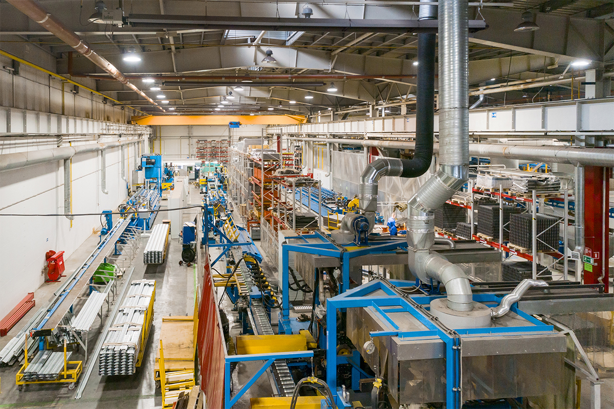
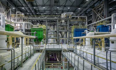
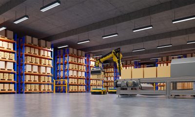
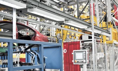
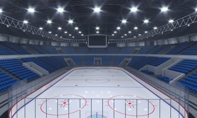
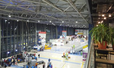
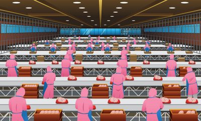
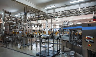
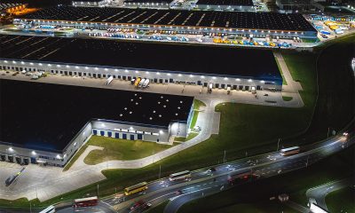
A high bay light is designed to provide general illumination in spaces with a minimum clear height of 6.1 m (20 ft). The high clearance between the floor and the ceiling is characteristic of manufacturing facilities, warehouses, distribution facilities, big box retail stores, convention centers, exhibition halls, airport hangars, recreation centers, and gymnasiums. Being utilitarian facilities, the clear height specification has significant implications. Higher clear heights mean more cubic capacity for accommodating large and tall equipment in industrial buildings, more vertical storage spaces for stacking and racking in warehouses, more flexibility to support future operations and storage needs as well as mission changes for multi-purpose facilities.
Along with increased height, however, come other issues. Hard-to-reach ceilings, expansive spaces, and long operating hours challenge lighting systems to deliver adequate illumination for safety, performance and productivity without excessive energy consumption and expensive lighting maintenance.
Disadvantages to HID lighting
Historically, high bay lighting had been a realm of fixtures that use high-intensity discharge (HID) light sources such as metal halide or high-pressure sodium (HPS) lamps. These lamp-based fixtures utilize round reflectors to produce a rotationally symmetric light distribution. The round design thus became the classic form factor of high bay lights. Despite their significantly longer lamp life and higher lumen packages than those that could be achieved with traditional incandescent lamps, HID fixtures have some inherent characteristics that render them incapable of meeting fast evolving codes and standards. These fixtures have a high optical loss (typically around 30%) which results in a poor luminaire efficacy, exhibit a high lamp lumen depreciation (LLD), perform poorly in color reproduction, and have a limited color temperature range. On top of that, the high relamping/maintenance frequency, long start-up and hot restrike process, and potential ignition problem (due to envelope failure) of HID fixtures are more of a concern for those managing industrial, retail, warehousing and gym facilities.
Advantages of LED lighting
The leap forward improvement in efficiency, performance and reliability makes LED lighting technology the logical choice for high bay lighting applications. With a light source efficacy exceeding 200 lm/W, LED lighting systems offer payback periods that are attractive enough to encourage a switch. LED lighting enables energy savings beyond improved source efficiency to offer an unprecedentedly high lighting application efficiency (LAE) because more effective delivery of light can be achieved through optimum optical distribution and utilizing advanced lighting controls.
A properly designed and engineered LED fixture can last more than 5 years in even the toughest environments. Maintenance-free operation over such a long life further improves the total cost of ownership. At the same time, improved uniformity of the lighting, flicker-free lighting, enhanced color rendering and customizable spectral composition of light contribute to optimum visual conditions which can significantly improve task performance and occupant safety in the operational environment. In contrast to HID lighting fixtures that take a long time to reach full brightness and usually fail prematurely under frequent on/off switching operation, instantaneous control over a wide range of intensity and robustness to high frequency on/off switching lend LED lighting systems perfectly to implementing sophisticated adaptive lighting solutions.
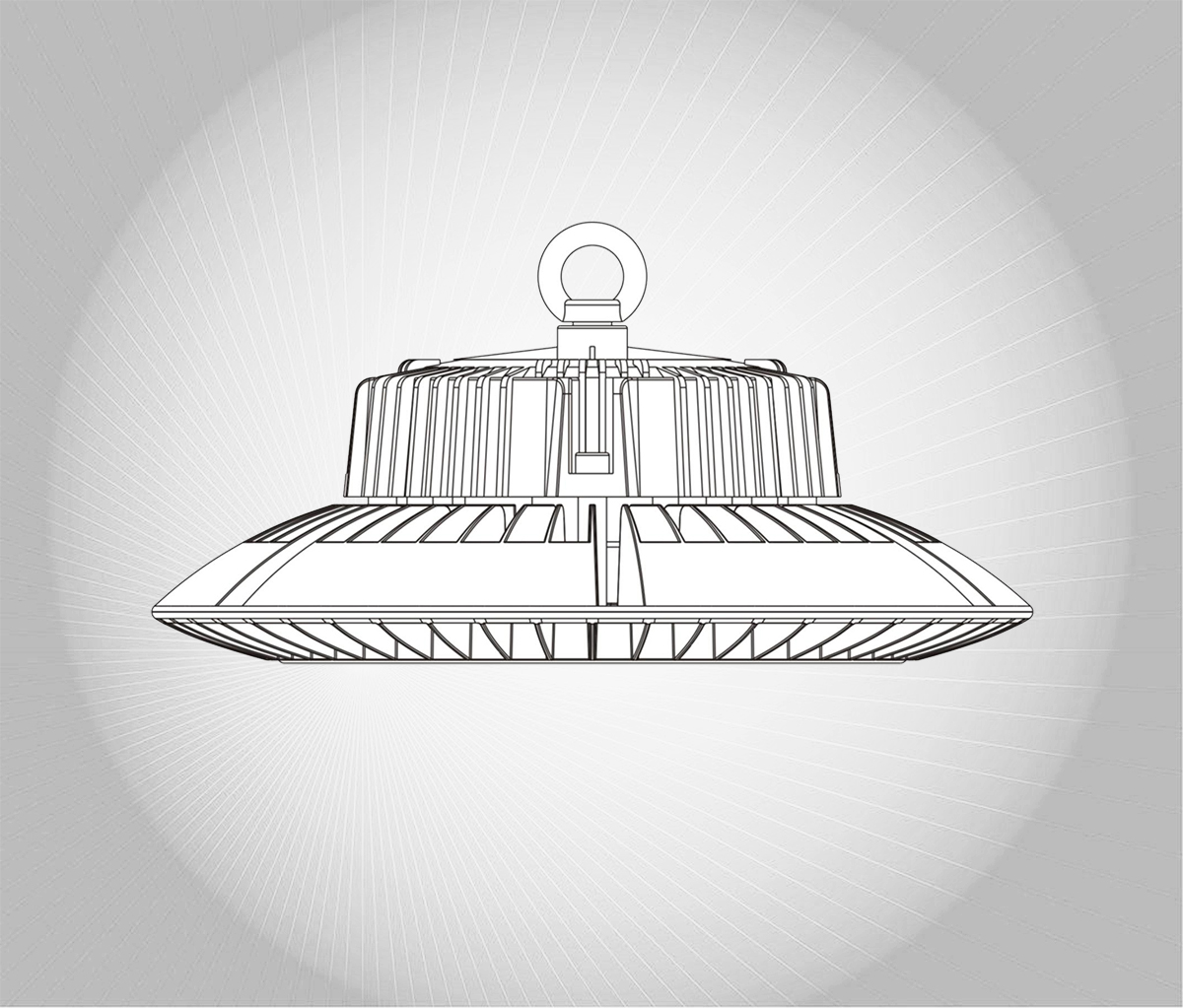
What is a UFO high bay light
LED technology platform enables high bay lighting to advance beyond legacy form factors. The first generation of high bay LED lights carried a retrofit design which uses a bulky reflector to control lumen distribution. This form factor was soon moved past to embrace a low profile design, which gave birth to “UFO” high bay lights. A UFO high bay light is defined as a round LED luminaire with a low profile achieved through a high level of integration of its optical, thermal, electrical and mechanical systems. It’s a fixture-as-heat-sink LED lighting system in which an array of LEDs are mounted to a large, compact heat sink. The directional nature of LEDs affords LED luminaires the chance to eliminate the use of reflectors and implement optical control directly from the source using individual lens optics.
The advantages of the “UFO” design are multifold. The large heat sink allows the heat generated in the LED junction to be spread out over a sufficiently large enough area to facilitate effective LED thermal management. Simultaneously, the “UFO” design creates a light emitting surface (LES) that is significantly larger than round retrofit high bay LED lights. With properly spaced LEDs, UFO high bay LED lights become surface emission devices which provide exceptional uniformity of lighting and maximizes fixture spacing. An additional benefits with the “UFO” design is that the compact form factor reduces packaging volume and facilitates transportation and storage.
Design and construction
A UFO or low profile round high bay LED light is comprised of a light assembly and a driver assembly. The heat sink is the most prominent part of the luminaire. It accommodates the LEDs and secondary optics to form the light assembly. The LEDs are typically assembled on a metal core printed circuit board (MCPCB) which is populated with circuit traces to provide electrical connectivity for the LEDs. The MCPCB simultaneously functions to provide electrical isolation and spread heat across the heat sink surface where it is attached to. The LEDs are populated in a density and pattern that ensures optimal light distribution while keeping high heat flux density below the saturation level of the PCB.
Control of light distribution from the high bay luminaire which incorporates a plurality of SMD LEDs is usually achieved with lens arrays. The lens array consists of a plurality of optical control units which are installed over each individual LED and regulate luminous flux from each LED through key vertical and horizontal planes. The use of TIR (total internal reflection) enables high bay lights to produce highly efficient and precisely controlled optical distributions. Lens arrays are molded from either PMMA (for maximum light transmission) or polycarbonate (for high thermal resistance). Aside from lens arrays, other types of lenses are available to control luminous flux from either an individual LEDs or an array of LEDs. High bay LED lights may be used in absence of secondary optics when the application involves a wide light distribution. The optical system also provides mechanical protection of the LEDs and plays an important role in the ingress protection (IP) of the luminaire.
In wet locations, high humidity or dusty environments, the optical lens is sealed to housing with a continuous silicone gasket. A high IP rating luminaire may come with an integral membrane vent which equalizes the internal/external air pressure to relieve seal stresses while blocking water and contaminants.
Thermal management
Thermal management is a significant concern for sustainability of high bay LED lighting systems because these systems often operate at a high power density and generate a considerable amount of heat that can raise the operating temperature if allowed to accumulate. Continuous operation of an LED at a junction temperature beyond what the LED is rated for will dramatically accelerate the degradation in LED packaging materials, resulting in rapid, irreversible lumen depreciation and shortened useful life. The “UFO” design allows heat generated by the LED packages to be transferred to the ambient environment via the shortest possible thermal path.
The thermal transfer path of a high bay LED light begins at the semiconductor junction of the LEDs, and travels via the MCPCB and heat sink before finally reaching the ambient air. Implementation of a robust thermal path in high bay lighting systems calls for higher reliability, high operating temperature capable solder joints or electrical interconnects between the LED packages and PCB. The dielectric layer of an MCPCB should be thin enough to guarantee a good thermal transfer from the LED yet still provide sufficient electrical insulation between the circuit and aluminum cladding. Thermal interface materials (TIMs) are often employed to completely fill interfacial air gaps between the circuit board and heat sink, thus minimizing interfacial contact resistance.
The heat sink of a high bay light is usually constructed from die cast aluminum. The die casting process offers the opportunity for cost effective heat sink manufacturing and provide flexible 3D geometry design capability for maximized convection surface area. When a thermal conductivity in excess of 120 W/m∙K is required, cold forged aluminum heat sinks should be considered. Most LED lighting systems rely on passive cooling (natural convection) because of its reliability and silent acoustics. When the thermal load of a high bay LED light is too high to be effectively dissipated by a heat sink with its size confined to a given footprint, heat pipes and/or active cooling technologies may be the last resort.
Light source
Selection of LED package platforms will sway in different directions depending on the lighting application, efficiency requirement, warranty period, and the customer profile. Oftentimes, energy efficiency is prioritized among the design and specification decisions for high bay lighting. As a result, plastic leaded chip carrier (PLCC) LED packages are widely incorporated in high bay lighting systems. The reflective plastic housing and leadframe plating allow these SMD LEDs to achieve a luminous efficacy exceeding 200 lm/W. High bay lights that use these types of LEDs can hit a luminaire efficacy as high as 180 lm/W. In contrast, products that incorporate ceramic based high power LEDs or chip scale package (CSP) LEDs have a considerably lower luminaire efficacy.
Despite a high initial efficacy and the use of higher thermal stability EMC housings, the PLCC LED packages often fail to smile the last laugh in heavy duty applications. When these LEDs are operated at high temperatures and bombarded by powerful blue photons from the LED chips, the plastic housing will decay and discolor at a rapid rate, leading to degradation in light output. High power and CSP LEDs often exhibit a much better lumen maintenance, which can be attributed to their high performance thermal design and absence of low thermal stability and photosensitive packaging materials.
The luminous efficacy of LEDs is also in a trade-off of color characteristics. A warm color and high color rendering index (CRI) are correlated with a low LED efficacy because of the Stokes loss and the eye sensitivity over the longer wavelength light. High bay LED lights usually have a correlated color temperature (CCT) greater than 4000K. Using a cooler light source is not merely intended to achieve a high efficacy, but also takes consideration of positive psychological and physiological stimulation from blue-rich radiation. The decision on the color rendering quality of a light source is balanced against the luminous efficacy of the light source. Typically, high bay lighting systems have a CRI in the range of 70s-80s.
LED driver
A high bay LED light has a round, rectangular or vertical driver assembly which sits on the light assembly while keeping the driver and LED light engine thermally isolated. The assembly can be a self-contained driver which has an integral metal housing or a driver housed in a serviceable electrical enclosure. In high bay lighting applications, it is critically important for the LED driver to provide high efficiency power conversion and operate to specifications under wide temperature and electrical ranges. Despite a higher cost, it’s often desirable to implement a two-stage topology which overcomes crucial limitations and challenges of the single-stage topology.
A two-stage LED driver has a dedicated stage for power factor correction (PFC) followed by a DC-DC converter stage implemented through a switch mode power supply (SMPS). Compared with its single-stage counterpart, a two-stage LED driver offers a suite of advantages, including a higher circuit efficiency, wider input range, wider dimming range, lower cost of EMI filter components, better surge protection, and lower output current ripple (flicker) characteristics. Consequently, two-stage topologies are the mainstream solution for high power LED drivers with power ratings in excess of 100W.
Lighting control
To help address the growing demand for controllability, LED drivers often incorporate constant-current reduction (CCR) and/or pulse-width modulation (PWM) dimming circuitry. Built-in dimming capability allows the lighting system to be used with various controls, e.g. occupancy sensors, daylight sensors and time clocks, for maximizing energy savings. Some dimmable LED drivers can be programmed for constant light output (CLO). This feature is designed to compensate for the depreciation of luminous flux and thus maintain a predefined lighting level throughout a luminaire’s useful life.
The analog (CCR) and digital (PWM) dimming circuitry can be controlled through a variety of protocols, such as 0-10V and DALI. The 1-10V dimming interface allows for simplified, one way lighting control, while the DALI interface provides greater flexibility with its bidirectional communication and individual addressing capability. High bay LED lights can also be configured and controlled individually or in groups through mesh networks that run on wireless communication protocols such as ZigBee, Z-Wave, and Bluetooth Mesh.


Loading...
New member
New member