What is an LED filament bulb
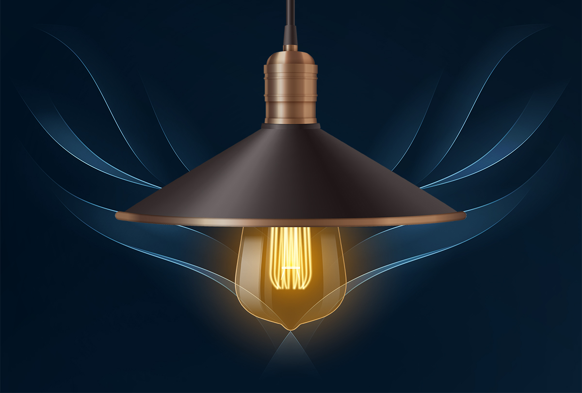
An LED filament bulb is a vintage-style light bulb that uses linear LED filaments as the light emitting elements to replicate the nostalgic look and feel of incandescent lamps while delivering significant energy savings over a much longer operational life. The history of electric lighting has been a continuous evolution punctuated by a series of thrilling innovations. Ever since Thomas Edison invented the incandescent lamp, our relationship to the physical universe during the absence of sunlight has been inspired by electric light. Incandescent lamps had been the standard for more than a century. These light bulbs emit light by dissipating heat in a resistive filament which produces visible light at the point of incandescence. The warm ambiance as a result of thermal radiation and the classic look of sparkling filaments in shimmering glass bulbs have become the staple elements of electric lighting. Even it’s now a technology of the past, the enduring charm of incandescent lighting remains treasured and will survive into the future.
Advantages of LED lighting
We now crossed the threshold of a new lighting revolution. At the forefront of today’s lighting conversations is solid state lighting (SSL) based on light emitting diode (LED) technology. Tremendous advancements enabled by LED lighting have driven a radical transformation in every conceivable lighting application. LED lighting overcomes many of the disadvantages of traditional technologies by taking advantage of semiconductor-based electroluminescent devices. Constructed from a combination of oppositely doped gallium nitride (GaN) layers, an LED is a p-n junction device that emits light through electron-hole recombination in its active region formed by one or multiple quantum wells. The quantum efficiency of electroluminescence produced by the semiconductor emitter can be very high. Typically, only 5% of the input energy is converted to visible light and the remainder is simply dissipated as radiant heat for an incandescent lamp. In contrast, typically more than 40% of the electrical energy supplied to a phosphor-converted white LED is converted to light. Not only do the LEDs outshine incandescent lamps with high efficacy lighting, but they also last tens of times longer than their ancestor. The profound design and application benefits enabled by LED lighting bring a whole new world of possibilities beyond basic illumination for vision and visibility.
Conventional LED bulb design
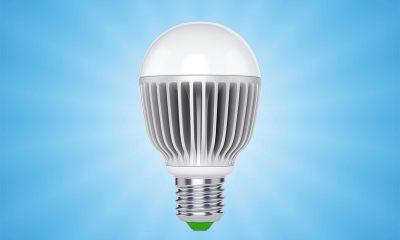
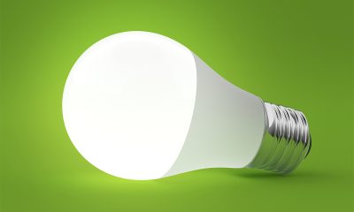
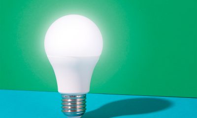
The world of LED lighting keeps getting more innovative. The evolution in LED light bulbs is a supreme example. Conventional LED bulbs are SMD LED systems that use plastic leaded chip carrier (PLCC) packages as the source of light. By nature, SMD LEDs are self-heating point sources that vary considerably from traditional technologies in electrical, thermal and optical engineering. In a typical configuration, these mid-power LEDs are solder mounted on a metal core printed circuit board (MCPCB) which consists of a dielectric layer sandwiched between a copper trace layer and an aluminum substrate. The LED assembly formed hereby is thermally interfaced with a heat sink which draws heat away from the LED junction. Due to the very high directional intensity of these discrete light sources, virtually all SMD LED bulbs use an opal (milky) PC diffuser to soften the excessively high luminance that is visually uncomfortable to the eye. The white PC diffuser dominates the look and feeling of LED bulbs that had been proliferating the market. Over time, people grew bored by the monotony and wished a product that could retrieve the ambiance and aesthetic of traditional lighting.
LED filament bulbs bring back the human dimension of lighting
The arrival of filament-style LEDs provided the opportunity to bring back the human dimension of lighting. A filament-style LED or an LED filament is a linear LED package designed to approximate the appearance of a tungsten filament. LED filaments have a package design similar to that of a chip-on board (COB) device. They are both fabricated using many small LED dies (bare semiconductor chips) that are electrically interconnected onto the package substrate. What set LED filaments apart from COB LEDs are the form factor, the package material, and the light emitting direction. A COB LED uses an MCPCB or a ceramic substrate mostly in a round or square shape. The backside of the package substrate is attached to the heat sink. Light is emitted from the front surface. An LED filament uses a linear substrate that is often in a length of 38 mm and a width of 1.5 mm. The substrate of a higher power LED filament may have a length of up to 50 mm and a width of 1.8 mm. The substrate preferably should be highly transparent so that light emitted by the LED dies will pass through the rear and from the sides of the substrate. A phosphor-silicone composite is then applied to cover the dies and all surrounding sides of the substrate. The linear array of LED dies pump phosphors within the filament package to produce white light with a light distribution pattern similar to that of a tungsten filament.
LED filament fabrication
At the core of the invention is the use of a linear package substrate. An LED filament is commonly referred to as a chip-on-glass (COG) package as it is made with a transparent substrate such as sapphire, glass, or ceramic. Metal substrates are rarely used. The most suitable substrate material should be highly transparent, highly thermal conductive, and of a low cost. Perfect things do not exist. A tough choice has to be made commonly between sapphire and other materials. From the performance perspective, sapphire is the preferred substrate material because of its superior combination of thermal, optical, chemical and physical properties. Sapphire is a single-crystal or monocrystalline form of aluminum oxide which is colorless and optically clear. With up to a 98.5% transmission and a broad transmission window from UV to mid infrared wavelengths, sapphire is optically superior to any standard glass. It’s also one of the hardest, most wear- and scratch-resistant materials. The thermal conductivity of sapphire 46 W/mK, which is a lot better than glass (1.4 W/mK). Despite a higher cost, sapphire takes up the majority of the market share. Trailing sapphire in the filament substrate market is ceramic which has a high thermal conductivity and lower cost. One of the most prevalent failure mechanisms in ceramic-based LED filaments is the delamination at the chip/substrate interface at elevated operating temperatures. Moreover, ceramic substrates are hard and brittle. Glass is just a finalist that is used only when the cost is extremely sensitive. Not all LED filaments are straight COG packages, flexible LED filaments are available to serve the purpose of creating lamps with an enhanced decorative effect. A flexible LED filament is made by die bonding a plurality of LEDs on a thin strip of a flexible printed circuit material such as polyimide (PI), polyether ether ketone (PEEK), polyester (PET), polyethylene napthalate (PEN), or polyetherimide (PEI).
LED die packaging
An LED filament has a plurality of LED dies connected in series. An LED die is a light-emitting stack that takes the form of the n-GaN/InGaN/p-GaN heterojunction. A conventional technique of making an LED die to grow the light-emitting stack epitaxially on a carrier substrate. Wire bonding is used to apply a bias across the n-type and p-type semiconductor layers, injecting electrons and holes into the active region where they recombine to generate light. The bond wire, however, is the weakest part of the LED die. It can break due to electrical overstresses, mechanical stresses or thermal cycling. Flip chip LEDs do not rely on conventional metal wire bonding for electrical connection to the electrodes. In a conventional configuration, photons are pumped from the junction through the epitaxial p-type layer. In a flip-chip configuration, the transparent carrier substrate, the n-type and p-type semiconductor layers are flipped downward the bottom. The p-type semiconductor layer becomes the bottom layer, and the transparent carrier substrate becomes the light transmissive layer. The anode and cathode electrodes are disposed on the bottom surface of the LED die. The connection between the n-type layer and the bottom cathode electrode is made using a metalized vias. The removal of wire bonding enhances the reliability of the p-n junction devices substantially. At the same time, the thermal resistance of the light-emitting stack is reduced because of the flipped epitaxial structure.
Configuration
An LED filament bulb has a configuration that is structurally similar to that of an incandescent lamp. The filament assembly is typically comprised of multiple straight LED filaments or a flexible LED filament that is usually styled as a spiral coil. Straight LED filaments are frequently arranged to run up and down vertically. They are symmetrically spaced around the longitudinal axis of the bulb to minimize the shadow cast by each other and to deliver substantially uniform illumination for a truly omnidirectional light distribution. The LED filaments are mechanically supported and electrically connected by lead-in wires. Different portions of a lead-in wire are made of different types of materials. The portion of wire that runs from the stem press to the filament electrode is made of nickel or nickel-plated copper. The Dumet wire which is composed of a nickel-iron core in an oxygen-free copper sheath runs through the stem press. It has a coefficient of expansion that closely matches that of the glass, which makes it possible to achieve a vacuum tight glass-to-metal seal. Copper lead-in wires form the last portion of the lead-in wires that run from the stem press to the LED driver. The glass stem is fused to the bulb after the filaments assembly is installed. The air is then pumped out of the glass envelope and a thermally conductive gas is introduced into the bulb through the evacuation tube which is subsequently sealed by a flame. The hermetically sealed bulb is fitted into the lamp base where the driver circuitry is located.
Thermal management
Thermal management poses the largest challenge to the longevity and performance of the LED filaments. The ability of an LED filament bulb to draw heat away from the LEDs is inherently limited because of the large thermal resistance in the path from junction to air. An SMD LED bulb is equipped with a dedicated heat sink to provide a high efficiency pathway for absorbing the heat generated from the semiconductor packages and for convecting the heat to the surrounding environment. By comparison, an LED filament bulb has to dissipate heat through a gas medium, which trails far behind aluminum in terms of thermal conductivity. The use of a highly thermally conductive gas is intended to transform the glass bulb into a heat sink. The glass bulb is filled with a helium gas or a blend of helium with another gas. Helium is an inert gas, with thermal conductivity higher than argon, neon, krypton, oxygen, nitrogen, and air. Passive thermal management with a gas medium alone usually does not remove a sufficient amount of heat to enable the LED filaments to operate at an adequately low junction temperature. The drive current, another variable that affects the junction temperature of an LED, must be tightly controlled to limit the amount of heat generated at the die.
Driver circuit
LED filament bulbs have an unusual limit to the driver circuit design. The physical constraint of the lamp base makes circuit miniaturization a necessity. Some products use a plastic extender to accommodate larger circuits, but this would influence the general vibe of the whole lamp. The LED driver for an LED filament lamp can be designed as a switch mode power supply (SMPS), a linear power supply, or the less commonly used capacitive power supply. An SMPS implements a DC-DC converter which regulates the LED load by controlling the duty cycle of a saturated power switch. A linear power supply provides constant current regulation by controlling the voltage drop across a power transistor biased in the linear region. A capacitive power supply or capacitive dropper simply steps down the mains voltage to a lower voltage utilizing capacitive reactance.
Switching regulation vs. linear regulation
SMPS LED drivers are single-stage systems that generally operate more efficiently and have a wider operating voltage window than the other two types. These LED drivers, however, have a higher parts count and EMI signature. Both linear and capacitive power supplies are step-down regulators. Capacitive circuits, because of their poor surge immunity and output quality, have been virtually eliminated by the market. Linear LED drivers occupy a sizable market share due to their simplicity and absence of EMI radiation. These resistive circuits work natively with phase-control (leading/trailing edge) dimmers which are designed for dimming resistive loads. When SMPS LED drivers are used with phase-control dimmers, pulse width modulation (PWM) must be applied to make the switching circuits responsive to the voltage signals. Although SMPS LED drivers offer a substantial efficiency advantage in applications with large headroom voltages, this advantage becomes less significant as this difference between input and output voltage is reduced. The headroom voltage is dissipated, which introduces an additional thermal load to the LED lamp. On the other hand, SMPS LED drivers dissipate almost no power. Linear driving circuits have a very narrow input voltage range. The amount of ripple in the output of a linear circuit can be considerable large, which may lead to visual anomalies such as flicker.
In general, linear circuits are used in low-cost designs. Switching circuits offer more room to improve their performance and are used in applications that require flicker-free lighting, multi-voltage operation, and/or full range dimming. To reduce the footprint, the LED drivers are made using integrated circuits or a combination of both ICs and discrete devices.
Color quality
A hallmark feature of incandescent lighting is its superior color quality. Tungsten filaments produce a compelling spectrum of light that closely matches that of a natural light source at the same correlated color temperature (CCT). Incandescent lamps deliver radiant power fairly broadly and uniformly across the visible spectrum, which translates to the ability to accurately render colors. At full rated power, an incandescent lamp produces a warm ambiance with CCT within the range of 2700K to 3300K. The spectral power distribution (SPD) of light produced by LED filaments can be engineered to reproduce the color quality of incandescent lamps. The cost is a lower luminous efficacy as opposed to higher CCT LEDs with a lower color rendering accuracy. This is primarily to the Stokes loss associated with converting the high energy blue light from the InGaN LED dies to the lower energy red light. The SPD is controlled by the phosphor down-converter. If different phosphors are used, the spectrum is balanced in right proportions across the visible wavelength range to provide the most accurate color rendition. However, the tradeoff between color quality and luminous efficacy in LEDs often leads to a compromise against the color rendering property and sometimes the warm ambiance.
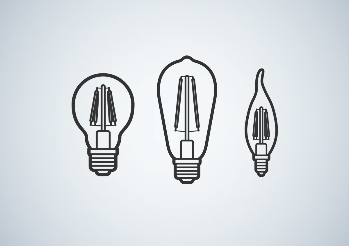
Base and shape
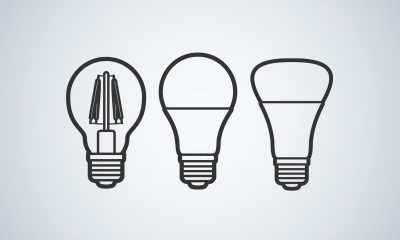
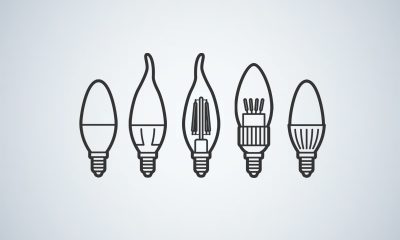
The glass stem and LED driver of an LED filament bulb are capped by a nickel-plated aluminum, brass or iron base. Lamp bases come in various specifications including medium screw (E26, E27), miniature candelabras (E11, E12), and double contact bayonet (B22). LED filament lamps are offered in a diversity of shapes and sizes. They range from GLS bulbs (A15, A17, A19, A21, A23), straight-tipped bulbs (ST15, ST18, ST19, ST20, ST52, ST58, ST64), globes (G14, G16, G16.5, G19, G25, G30, G40, G50, G63), reflectors (R50, R63, R80), tubes (T10, T14, T19, T20), blunt tip bulbs (B8, B10, B11, B13), bulged bulbs with angular (bent) tip (BA10, BA11), candle-shape bulbs with bent tip (CA5, CA7, CA8, CA10, CA11, CA17) and bulged tubular lamps (BT15, BT28, BT37, BT56) to pear-shape bulbs with straight neck (PS25, PS35).


Loading...